When you click on links to various merchants on this site and make a purchase, this can result in this site earning a commission. Affiliate programs and affiliations include, but are not limited to, the eBay Partner Network.
The car is from 1991.
Last night I attempted to install the Deatshcwerks Fuel Pump Hardwire Kit. However, I cannot get the pump to prime by using my ECU signal as the trigger. With the stock wiring and relay, my ECU would prime the pump correctly.
I did my best to follow these two threads: aidandj's install and pdexta 's install.
My goal was to bypass the stock relay wiring entirely but I'm not sure what I did wrong. I ran a new ground for the pump because the stock one was chewed up. Only about 5 strands holding it together. The new ground goes from the bottom black wire to the chassis ground bolt behind the driver's seat where it looks like the chassis harness grounds. Does the ECU fuel pump not actually provide 12V but instead just grounds the relay in a stock configuration? If I rewire the DW kit to use the stock fuel pump power wire as the trigger the pump works so I assume all my other connections are correct. Am I grabbing the wrong signal wire of the ECU? I was referencing trubokitty.com for the wiring harness, it lists the fuel pump wire as R/W, but mine was solid red. The best I can tell all my other ECU wires around it matched. Im still very green to wiring and any help is appreciated.
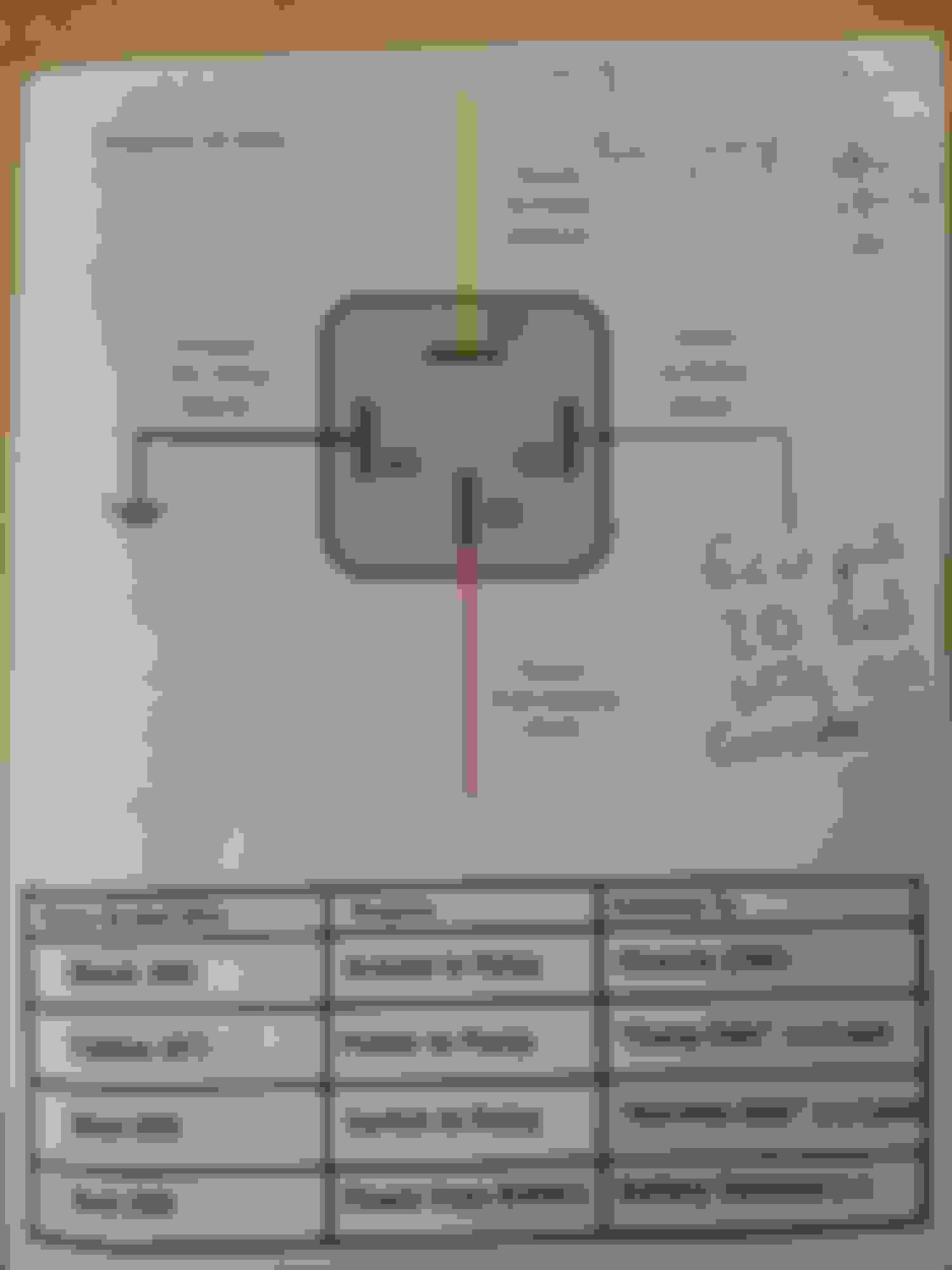
85 and 86 go to a coil that needs a differential of 12V to actuate. ECU fuel pump output grounds the circuit. Wire 85 to 12V, and 86 to ECU output. You may be able to do 86 to 12V, and keep 85 on the ECU output, I forgot if relay coils are directional.
85 and 86 go to a coil that needs a differential of 12V to actuate. ECU fuel pump output grounds the circuit. Wire 85 to 12V, and 86 to ECU output. You may be able to do 86 to 12V, and keep 85 on the ECU output, I forgot if relay coils are directional.
I think I have probably misidentified 2O as the wire I want. Here is a photo of that specific connector. I have added the two red wires on the left for sequential fuel. That is the only modification I have made to this connector. I do not have the stock AFM and I have added a jumper at the AFM connector to get the fuel pump to prime. As it sits right now my fuel pump works but it is using both relays. The stock one and my new one, which is redundant and why I want to use the ECU pinout to trigger my new relay. I cant follow that wiring diagram well enough to know what pin I should be using. What pin should I be using at the ECU?
It is a Reverent MS2 Enhanced. No, I have not modified the FP1 circuit. I do not know which pin on the OEM connector is the output of the FP1 circuit. Car was 100 percent stock when I got it. Bought the MS2, followed the basic steps everyone does for a megasquirt install and I was off and running.


 0
0