
ITT: fmic size and piping diameters for optimum efficiency


That core is pretty long and skinny. I would think that would have quite a bit of pressure loss. And most of the core isnt really doing much to cool the air. Remember, heat only moves hot to cold and the bigger the pressure differential the faster it transfers. I havent done the math, and I have no intention of doing it for a while but I would hypothesize that only the first 10 inches of the core provide 90% of the cooling. The other 18 are really just extra drag. Again, haven't done the math here, by my gut says something like a 18x8x2.5 core with the flow in the 8 direction. Thats the same frontal area and volume would would flow a **** load more and have a much lower pressure drop..
Reply
 0
0

0

Elite Member
Joined: Jul 2005
Posts: 6,420
Total Cats: 84
Remember that the volume flow rate of air is the same in the pressurized side of the compressor, as a stock motor. The cfm is the same as a stock motor:
A good estimate for volume flow at peak power is
90% * 6000 RPM / 2 * displacement
It is the *mass* flow rate that is increased, due to boost. (and of course, the cfm at the compressor inlet). When calculating pressure drop across piping, make sure that the equations you use, use the (increased) viscosity of air at the boost pressure you will run.
Reply
0
0

Ok, so help me out here:
2001 vvt engine completely stock
2860rs disco potato on a longtube mani and well flowing 3" exhaust (ewg too)
Since stock engine boost will be 10-12psi tops. Goal is about 250whp
Car is on e85 which probably doesn't matter
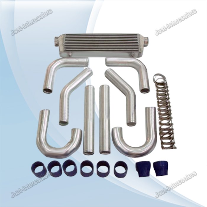
The setup I posted with very smooth 2" mandrel bent piping, pretty much 3 bends, and a 22x5.5x2.5 bar/plate core with 2" in/outlets.
Is it small?
Just right?
?????????
To be COMPLETELY honest, the biggest reason I'm leaning towards this is packaging. The intercooler will fit perfectly, and the piping will be much easier to route than 2.5".......The supposed better response from smaller pipping is not my goal, but I wouldn't mind better response, even if just barely
2001 vvt engine completely stock
2860rs disco potato on a longtube mani and well flowing 3" exhaust (ewg too)
Since stock engine boost will be 10-12psi tops. Goal is about 250whp
Car is on e85 which probably doesn't matter
The setup I posted with very smooth 2" mandrel bent piping, pretty much 3 bends, and a 22x5.5x2.5 bar/plate core with 2" in/outlets.
Is it small?
Just right?
?????????
To be COMPLETELY honest, the biggest reason I'm leaning towards this is packaging. The intercooler will fit perfectly, and the piping will be much easier to route than 2.5".......The supposed better response from smaller pipping is not my goal, but I wouldn't mind better response, even if just barely
Reply
0
0
Elite Member
Joined: Jul 2005
Posts: 6,420
Total Cats: 84
My guess is the i/c will be the major bottleneck, not the piping. I've measured pressure loss in my old AVO piping and it was on the order of 0.5 psi total, at 220 whp. It was 2.25" IIRC. That was with about 6 90* bends.
Intercoolers vary a lot in pressure loss and cooling efficiency, even for the same cross-sectional area in charge-air tubing, and length. This is because the internal construction details make a huge difference - the type of turbulators and end tank shape.
The i/c you posted seems skinny to me; just comparing it to typical i/c sizes of those who post good numbers (for the boost level), at 250 whp. My old AVO system was pretty well designed and put out very good numbers for the boost and the turbo, and its i/c was 9x16x3", for ~225 whp.
Bottom line, without actual data on the i/c you don't know.
Reply
0
0
This is 100% a guess, since it is 100% ebay, and therefore 100% untested. We are speculating based completely on size, shape, and design "style".
I do appreciate the input though, and welcome more of it. In the end I'll post results of whatever I end up with.
What makes you say its a bottleneck? Because its wide and short? Or the 2" openings? Or both?
So a narrower, taller, ic with bigger openings and tapered couplers (from 2" piping to 2.5" inlet/outlet) would, in your opinion, be more ideal?
Reply
0
0

Elite Member
Joined: Jul 2005
Posts: 6,420
Total Cats: 84
I say the i/c will be the bottleneck because it is, in all cases I've seen data for - i.e. the pressure drop in the i/c is greater than that of the piping. And again, because the i/c in your pic has much smaller flow cross-sectional area to charge air, than other known good setups at 250 whp. My AVO for example, had about 45% x 9" x 3" or about about 12 square inches.
Reply
0
0
Elite Member
Joined: Jul 2005
Posts: 6,420
Total Cats: 84
Some of the earlier posts about calculating pressure loss in the charge pipes for the cfm are wrong because they use the volume flow rate of the compressor inlet, and AFAICT assume 1 atmosphere.
At 140 hp the stock 99 motor will flow something like 180 cfm. With forced induction the volume flow rate is the same, but the air density is higher. Again the right way to calculate is to use 180 cfm but using air viscosity at the increased pressure. I'm guessing that with 6 or so bends, most of the pressure drop will be in the bends so you can resort to calculating just the losses in the bends. The proper equation will need the diameter, bend radius, flow, and density/viscosity@boost.
At 140 hp the stock 99 motor will flow something like 180 cfm. With forced induction the volume flow rate is the same, but the air density is higher. Again the right way to calculate is to use 180 cfm but using air viscosity at the increased pressure. I'm guessing that with 6 or so bends, most of the pressure drop will be in the bends so you can resort to calculating just the losses in the bends. The proper equation will need the diameter, bend radius, flow, and density/viscosity@boost.
Reply
0
0

Doubt the 2560 would hold power to redline, also because I found a 2860 and the rest of the setup to go along with it for a great price. Its t3 and in my opinion is a very nice setup that I expect to work very well.
Reply
0
0
my most recent idea:
2" piping from the 1st pic I posted + 28x7x2.5 IC from the 3rd pic I posted. After poking around in the NB2 front end, there is more than enough room for a taller core, and routing will be much easier with the 2" piping.
I'm pretty set on this and if anyone has any more input speak now or forever hold your peace.
Reply
0
0


Thread
Thread Starter
Forum
Replies
Last Post
stoves
Suspension, Brakes, Drivetrain
5
Apr 21, 2016 03:00 PM


