
Map Sensor feed position vs. output


Thread Starter
Elite Member
iTrader: (8)
Joined: Dec 2008
Posts: 2,910
Total Cats: 51
From: Kingston, Ontario
Have any of you guys spent any time trying different areas inside the plenum for a MAP sensor reading? Being that we are all retrofit and no pressure sensor it has me wondering how much the location of the vac source changes the output to the MAP front to back of plenum.
Cheers,
Matt
Cheers,
Matt
Reply
 0
0

0

Thread Starter
Elite Member
iTrader: (8)
Joined: Dec 2008
Posts: 2,910
Total Cats: 51
From: Kingston, Ontario
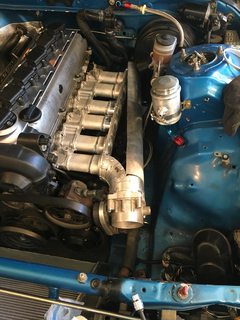
Non-Miata related question. Just a general question. Im building an intake manifold for my personal car. (small photo below of concept)
Wondering where I can get the most stable yet proper representation of MAP or if its a non-concern. The sensor I'm using is a tMap though so I am pretty limited on where to put it (pretty much right behind the throttle body would be the best temperature reading)
Photo
Wondering where I can get the most stable yet proper representation of MAP or if its a non-concern. The sensor I'm using is a tMap though so I am pretty limited on where to put it (pretty much right behind the throttle body would be the best temperature reading)
Photo
Reply
0
0

Elite Member
Joined: Oct 2011
Posts: 3,693
Total Cats: 222
From: OKC, OK
Looks similar to the way alot of custom BMW guys build manifolds.
I'd be more concerned about equal flow to all runners, years ago on R3V someone was building proto's like this, and his simulation software was showing it hard to get a good balance.
I'd be more concerned about equal flow to all runners, years ago on R3V someone was building proto's like this, and his simulation software was showing it hard to get a good balance.
Reply
0
0


If it's worth anything to you, I ran an external AEM Map sensor to a small port behind the throttle body, before the runners with nipples that looked like they'd normally be purposed to the FPR or Cruise Control. This is on a square top. As I recall, it's around the same area that the Megasquirt manuals would recommend running a loooooooong skinny line to.
Reply
1
1


