
One size up on the turbine AR killed spool (t3 content)

Thread Starter
Elite Member
iTrader: (5)
Joined: Jan 2005
Posts: 7,486
Total Cats: 372
From: Atlanta
I'm running a T3/T4- specs are compressor 70AR 50 trim, turbine 48AR Stage III wheel. It's mounted on a long tube equal length turbo manifold. The turbine housing was a stock Mercedes piece with the accompanying internal wastegate. Feeding the arrangement was a 1.6 Miata plenum grafted to stock FE3 runners, capped by the stock Miata throttle body. Exhaust is 3 inch all the way with high flow cat, 18" glass pack and giant magnaflow straight-through. Spool was tolerable since it built some pressure lower in the rpm like this:
rpm - kpa
2500 - 114
3000 - 133
3550 - 169
3750 - 187
4000 - 210
This time around I changed the turbine housing to a 63AR and added a 38mm external waste-gate. Manifold and exhaust are the same - 3 inch all the way. Intake side is now an aftermarket DSM Magnus plenum (designed for a boosted 2.0L) with a 65mm Ford throttle body. Now my spool looks like this:
rpm - kpa
2700 - 110
3700 - 127
4100 - 140
4700 - 205
4720 - 230
Spool is the same regardless of reference line connections (or disconnected) and using or not using EBC.
I have checked every part of the system and can't find anything wrong. Pressure check from the turbo inlet to the TB was excellent (only two pipes). BOV not leaking. There were no pre-boost leaks in the exhaust. EWG preload and seat seal were excellent. EWG action check out wonderful with controlled air pressure (cracked at 7psi and fully open by 8). The turbo is in excellent condition with extremely little shaft play (like new journal bearing), excellent wheel to housing clearance on the compressor and turbine. So at this point I can only assume that the AR change is primary cause of this spool change. Is it possible? Turbo experts educate me!
rpm - kpa
2500 - 114
3000 - 133
3550 - 169
3750 - 187
4000 - 210
This time around I changed the turbine housing to a 63AR and added a 38mm external waste-gate. Manifold and exhaust are the same - 3 inch all the way. Intake side is now an aftermarket DSM Magnus plenum (designed for a boosted 2.0L) with a 65mm Ford throttle body. Now my spool looks like this:
rpm - kpa
2700 - 110
3700 - 127
4100 - 140
4700 - 205
4720 - 230
Spool is the same regardless of reference line connections (or disconnected) and using or not using EBC.
I have checked every part of the system and can't find anything wrong. Pressure check from the turbo inlet to the TB was excellent (only two pipes). BOV not leaking. There were no pre-boost leaks in the exhaust. EWG preload and seat seal were excellent. EWG action check out wonderful with controlled air pressure (cracked at 7psi and fully open by 8). The turbo is in excellent condition with extremely little shaft play (like new journal bearing), excellent wheel to housing clearance on the compressor and turbine. So at this point I can only assume that the AR change is primary cause of this spool change. Is it possible? Turbo experts educate me!
Last edited by m2cupcar; Jun 12, 2017 at 10:41 PM.
Reply
 0
0

0


Joined: Apr 2014
Posts: 18,643
Total Cats: 1,870
From: Beaverton, USA
Reply
0
0

Thread Starter
Elite Member
iTrader: (5)
Joined: Jan 2005
Posts: 7,486
Total Cats: 372
From: Atlanta
I agree that with the larger AR the spool will be worse, but not by this much. The primary changes are the EWG and turbine housing size.
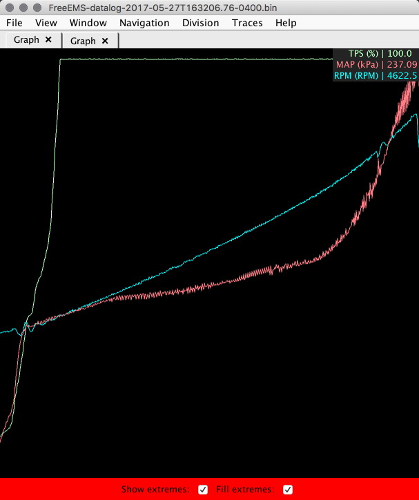
I considered the gate might be blowing open- to the point that I ordered a 14psi spring for EWG. But what doesn't make sense is that a 7psi spring is blowing open at 112kpa. Below you can see the boost curve rises to 112kpa and then tapers off until just over 130kpa- then it takes off. Is it blowing open at 112kpa? This curve looks the same regardless of EWG control- straight reference signal to the WG, no signal, EBC... I also considered lowering my boost cut a bit and making a plug to cap off the EWG port to see what spool does. That would be easier than bringing back the .48AR turbine housing as mentioned below.
The prior 48AR housing is a different 5-bolt pattern than the current 63AR turbine housing. Swapping back to the old setup requires making a new turbine-to-downpipe adapter comprised of a flange, pipe and v-band. I considered it. But I can't deny the lure of improved spool for street driving. I have a turbo capable of 400+ whp and don't care for much more than 300whp on a stock internals engine. So I am leaving a bunch of lower rpm power on the table with this turbo. What I don't want to do is throw another smaller turbo on and find that it's spooling 800rpm later than expected.
Right now it's all apart. I suppose the next logical step is put it back together, install the new 14psi spring and log some pulls in hope of a new/improved boost curve. I'm assuming that doubling the spring rate is adequate for keeping the gate shut. Otoh - am I foolishly denying my opportunity run an appropriately sized turbo?
Last edited by m2cupcar; Jun 12, 2017 at 10:47 PM.
Reply
0
0

I could be wrong, but I believe each turbine housing is machined for a specific trim turbine wheel. So if your larger AR housing is machined for a larger trim wheel....
I bring this up because I run the largest t25 trim turbine wheel and the exducer diameter is much larger than the common trim wheel. If you were to run the large trim housing on the small trim wheel it would probably have the effect you are seeing.
I bring this up because I run the largest t25 trim turbine wheel and the exducer diameter is much larger than the common trim wheel. If you were to run the large trim housing on the small trim wheel it would probably have the effect you are seeing.
Reply
0
0

Thread Starter
Elite Member
iTrader: (5)
Joined: Jan 2005
Posts: 7,486
Total Cats: 372
From: Atlanta
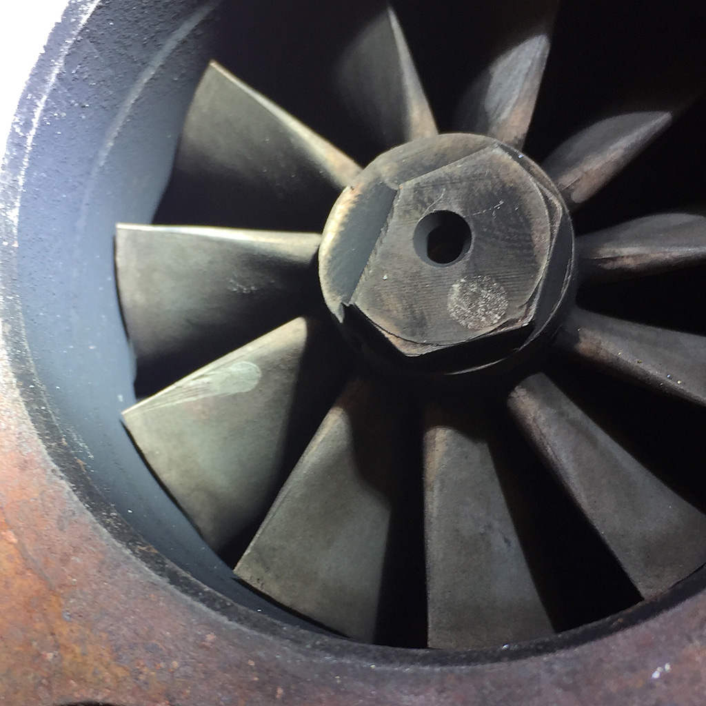
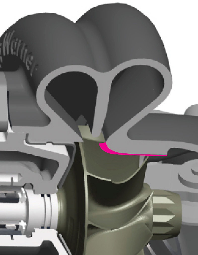
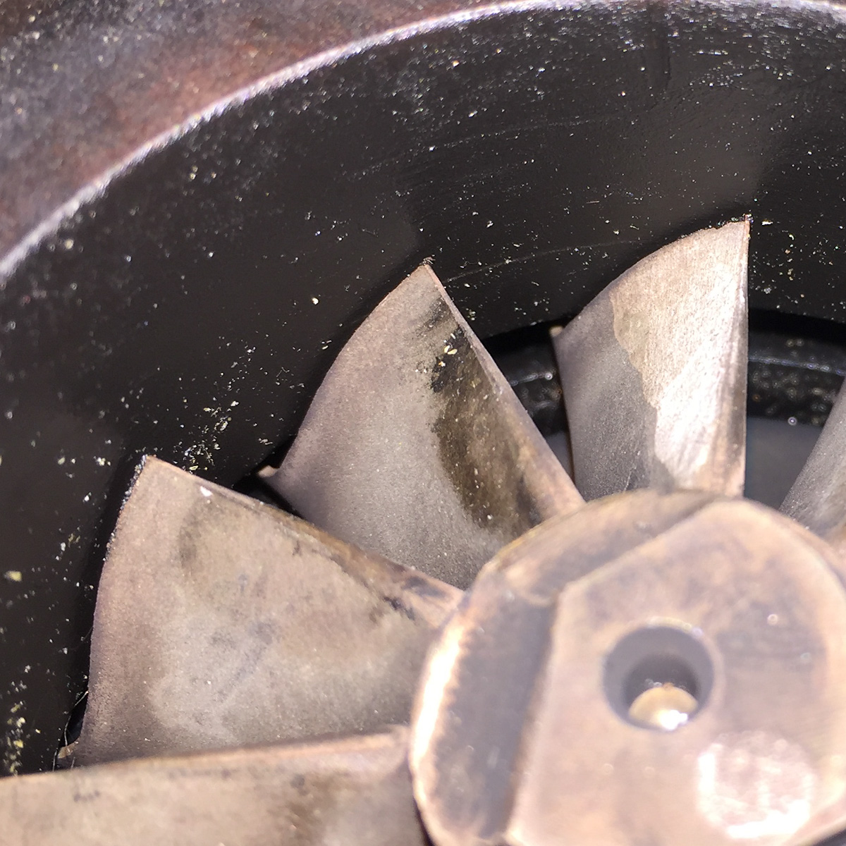
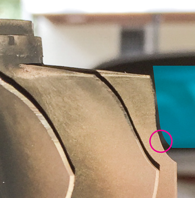
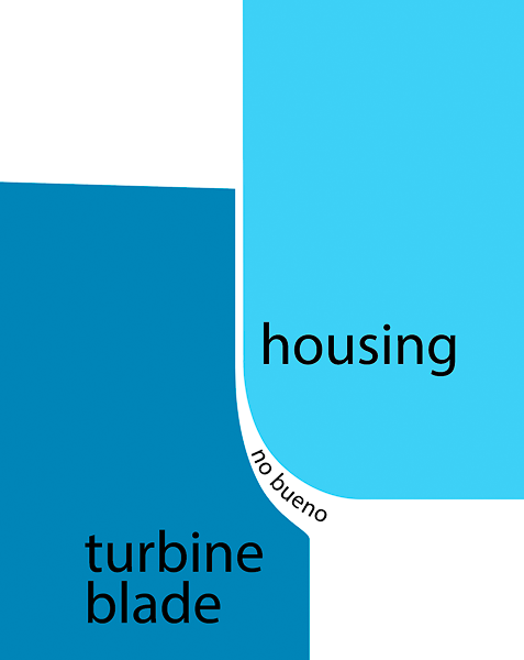
Is there a known technique for locking a EWG shut? I didn't find anything on google. May be easier to "cap" the EWG port (I may have a 38mm EWG vband ring) or use a hole-closed-up washer. Agree- that would prove/disprove WG issue. BUT...<br /><br />leboeuf spurred me to reinspect the turbine wheel vs. housing. I visually checked it way back, and again this time. Thought it looked good until I enlarged some phone pics. Went back out and shot some more below. It looks to me like the turbine major is deviating from the housing wall based on these new pics. I assume that this part of the housing contour is a constant around the entire circumference. Went through google images for turbine cutaways and it looks that way. Image below shows what I believe the fin/housing tolerance is doing based on these photos (using a BW turbine for my purpose). I'll pull this 63 housing and install the 48 next- then attempt to shoot same pics to confirm/deny the difference. 
turbine wheel/housing fit looks good at the minor
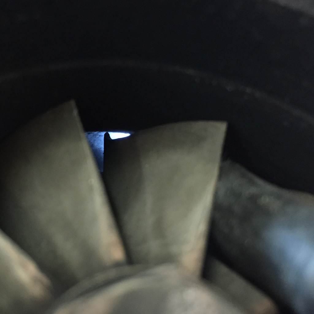
but deep inside it looks like the minor/housing gap is too large?
what I think the gap looks like
I think I have to do as Sav suggested and go back to the 48AR housing.
And here's a torque graph of the current setup:

turbine wheel/housing fit looks good at the minor
but deep inside it looks like the minor/housing gap is too large?
what I think the gap looks like
I think I have to do as Sav suggested and go back to the 48AR housing.
And here's a torque graph of the current setup:
Last edited by m2cupcar; Jun 13, 2017 at 10:33 AM.
Reply
11
11

Thread Starter
Elite Member
iTrader: (5)
Joined: Jan 2005
Posts: 7,486
Total Cats: 372
From: Atlanta
I did that. No change, same boost curve. I think I tried everything conceivable with the EWG and reference lines.
I mounted the CHRA in the 48AR housing and it looks very similar to the 63AR.
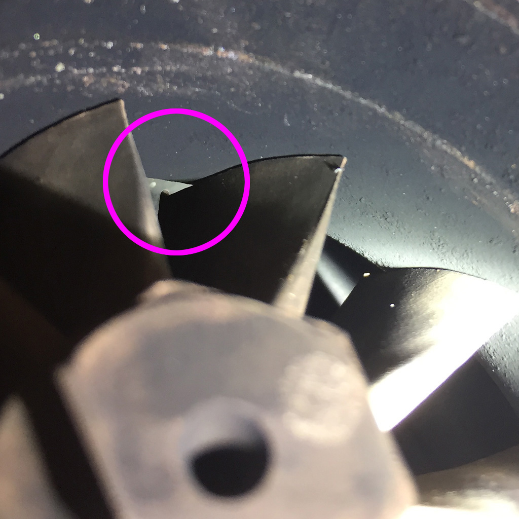
The primary difference in the housings (circled) on the wheel side is at the major/minor transition - 63 has a radius transition and the 48 is angled straight edge.
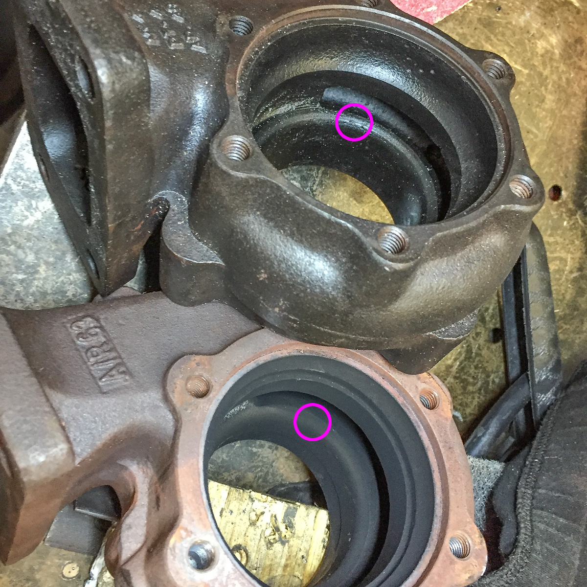
But looking at the wheel- you'd think the radius is preferable. Unfortunately I don't think this is the issue.
What next? I can install it with the 48AR, then verify it against prior 48AR setup and current 63AR setup spool. If the spool still sucks, I can add the 14psi spring (came today). I just have to build another housing flange to downpipe adapter because the 48AR uses a different bolt pattern and is ~.125" narrower. Otoh I could abandon this turbo and the bastard turbine housing all together, pick up a new, smaller t3/t4 china charger and bolt it up.
I mounted the CHRA in the 48AR housing and it looks very similar to the 63AR.
The primary difference in the housings (circled) on the wheel side is at the major/minor transition - 63 has a radius transition and the 48 is angled straight edge.
But looking at the wheel- you'd think the radius is preferable. Unfortunately I don't think this is the issue.
What next? I can install it with the 48AR, then verify it against prior 48AR setup and current 63AR setup spool. If the spool still sucks, I can add the 14psi spring (came today). I just have to build another housing flange to downpipe adapter because the 48AR uses a different bolt pattern and is ~.125" narrower. Otoh I could abandon this turbo and the bastard turbine housing all together, pick up a new, smaller t3/t4 china charger and bolt it up.
Reply
0
0

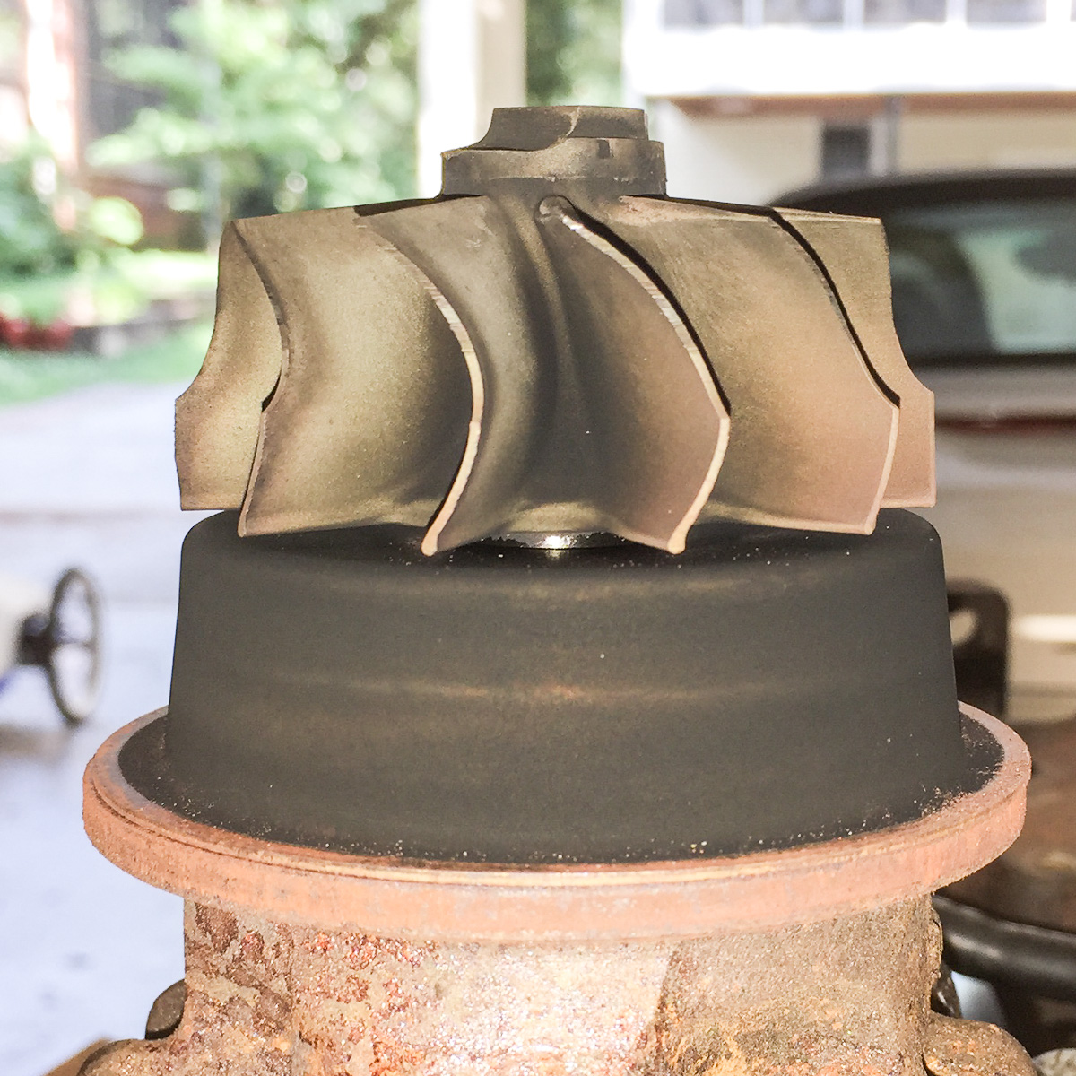
If you want to be super doubly certain that the housings match the wheel similarly, check the axial blade clearance.
The process goes like this. Put the CHRA on its end with the turbine wheel facing up. Get a couple of little pieces of solder and bend them around the edge of two opposing blades, as close to the corners of the blades at the inducer (major diameter) end as possible. It might take a little fiddling but you should be able to get these little ******* to cling onto the edges of the blades.
Then lower the turbine housing over the turbine wheel. You'll knock the solder off a few times before you get it right and the solder stays put. Then push the housing into place and snug down a couple of the turbine housing bolts. Then disassemble and measure the squished part of the solder with calipers. You might have to open up the solder to get the jaws in there, which is fine as long as you don't bend the bit you squished.
Reply
0
0
Thread Starter
Elite Member
iTrader: (5)
Joined: Jan 2005
Posts: 7,486
Total Cats: 372
From: Atlanta
Solder goes near the circle where the housing (blue) begins to fall away from the blade as below? And what kind of tolerance am I looking for. I can tell visually that once the curve in the housing/wheel blade begins the tolerance starts to increase, and continues to grow.
Reply
0
0
Solder goes near the circle where the housing (blue) begins to fall away from the blade as below? And what kind of tolerance am I looking for. I can tell visually that once the curve in the housing/wheel blade begins the tolerance starts to increase, and continues to grow.
The clearance will vary depending on manufacturer. In your case, you are simply looking to determine if there's a big difference in clearance between the two housings. I forgot to add that, you should push the rotating group toward the turbine side to bottom out the thrust bearing after you've snugged the housing down.
Hook the solder around the blade as close to the inducer corner as possible. Like this (red mark):

Reply
1
1
Thread Starter
Elite Member
iTrader: (5)
Joined: Jan 2005
Posts: 7,486
Total Cats: 372
From: Atlanta
I suspect the larger 63AR housing is worse.Too big to measure with solder.
 Do you think that's adequate for the lazy spool?
The 48AR housing was an OE Mercedes piece that was cut for a stage III wheel by a turbo rebuilder. The 63AR has a Turbonetics "T" brand on it, but that's about all I know. Possible both were suited for the originally mated turbines, but not for this genuine Garrett wheel. Oh well.
edit: I was wrong about the 63AR, it does not have the Turbonetics "T" on it. I confused it with yet another turbine housing I had laying around. This 63AR has nothing on it but a 63AR, so I assume it is chinese/eBay.
Last edited by m2cupcar; Jun 30, 2017 at 08:08 AM.
Reply
0
0

Thread Starter
Elite Member
iTrader: (5)
Joined: Jan 2005
Posts: 7,486
Total Cats: 372
From: Atlanta
I should, in theory, be able to buy a Garrett T3 turbine housing for a Stage III wheel and have a good fit. Of course I'm assuming this is a genuine Garrett turbo purchased from a former forum vendor TunerToys. They seemed legit.
Or is it like this with the larger inducer/major with a proper blade/housing gap?
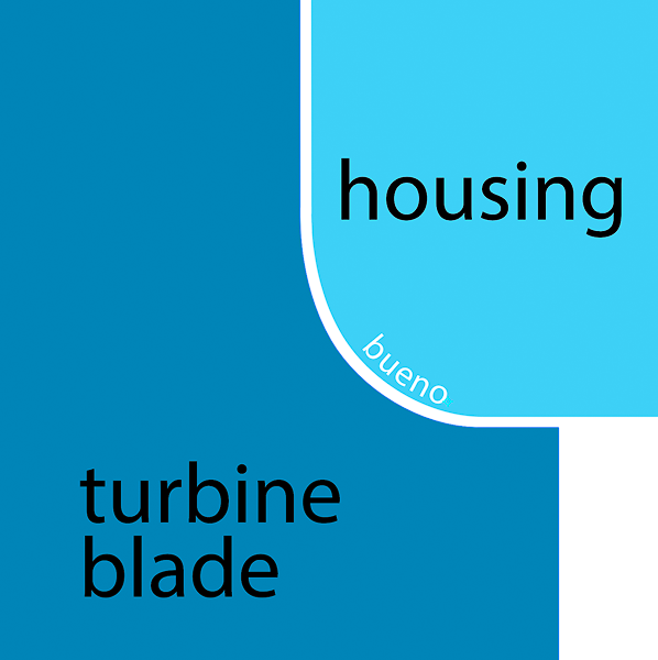
Or is it like this with the larger inducer/major with a proper blade/housing gap?
Reply
0
0
i never looked at the gap, im assuming it was profiled correctly -- turbine housing was an exact replica. The wheel profile itself was exactly the same as my legit garrett wheel just extended out much further.
i have pics, just dont think they are online.
i have pics, just dont think they are online.
Reply
0
0


