Intake Manifold Design Question
 05-09-2009, 11:44 AM
#1
Elite Member

Thread Starter
iTrader: (7)
Join Date: Apr 2006
Location: VaBch, VA
Posts: 6,451
Total Cats: 322
This is purely out of curiosity, not advocating better/worse design, simply putting it out there for discussion.
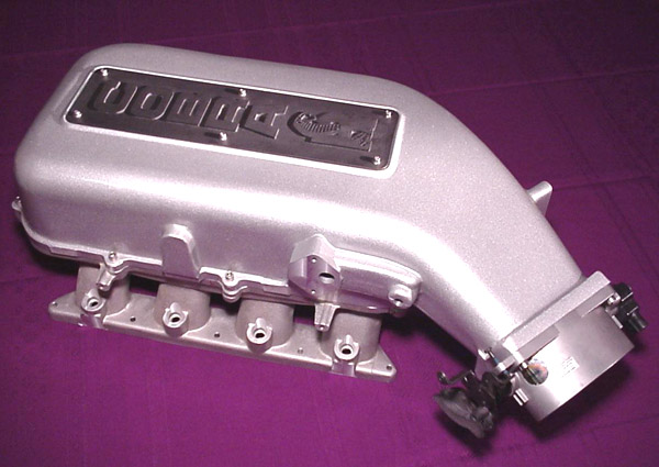
I was doing my homework on IM's, trying to learn the physics and engineering behind runner length, frequency, plenum volume, resonance order, blah blah blah... and discovered that every single aftermarket Miata IM I'd seen has the TB on the front of the IM. It makes sense due to packageing constraints to bring the coldisde pipe straight up the back of the radiator and use a 90* coupler to turn the air into the TB... or over the top, TDR style.
Then I started thinking about how some guys take their hot-side pipe and run it through the fender... and why couldn't you do that on the intake side. I did a Google image search and found a few examples, but made a paint too. You could even angle the thing down and come up behind the alternator... there are a few options.
It would only make sense if there was a flow advantage, and that's where I need somebody smart to take over. I know that Brain and a few others have done some airflow modeling and found it difficult to get good flow into the #4 runner on front-mount units.
I'd like to hear some thoughts on a side-mounted throttle-body.

Reply
 0
0

0


/Madpsi%20-%20Pouyas%20MR2%20-%20Inside%20intake%20manifold%201.jpg)

 05-09-2009, 01:06 PM
#6
Boost Czar

iTrader: (62)
Join Date: May 2005
Location: Chantilly, VA
Posts: 79,508
Total Cats: 4,080
With a side mounted throttle body you have to worry about the shock tower being in the way. If you raise it, I dont think the hood will close.
a teardrop shape is a great shape for flow. Corky also fooled around with something similar with the TB pointing straight down.
Reply
0
0
05-09-2009, 01:30 PM
#7
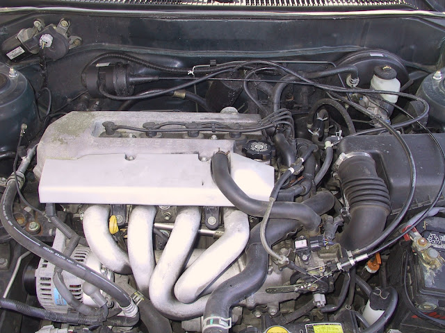
If I was designing an intake manifold I would make it look like the the turbo manifold. Obviously the exhaust wouldnt be cast, but they would both be tubular and designed in a way that would make it work as both an exhaust and an intake. More for artistic reasons then anything else.
Reply
0
0

 05-09-2009, 03:29 PM
#12
Boost Pope

iTrader: (8)
Join Date: Sep 2005
Location: Chicago. (The less-murder part.)
Posts: 33,072
Total Cats: 6,626
I was just about to say "You know, I've always wondered about a tubular design, like an exhaust header in reverse..." and I see this.
Assuming steady-state flow, such a design would seem to be ideal. I say this based solely upon the fact that the distance and geometry between the throttle and the intake port is equal for each cylinder, as opposed to most OEM designs where one port is right next to the plate, and another is some great distance away next to a wall.
I admit however that my grasp of fluid dynamics in a pulsed environment is tenuous at best.
Is there among us any real-world experience with such a design, or perhaps even better, a computer-aided analysis of its performance at various RPMs?
Reply
0
0
05-09-2009, 03:54 PM
#13
Boost Czar
iTrader: (62)
Join Date: May 2005
Location: Chantilly, VA
Posts: 79,508
Total Cats: 4,080
I'd assume it would choke up at high rpms. but im also an advertising major. You would more than likely see high vacuum at idle and get great throttle response but less overall power output due to the lack of available volume due to no plenum. Your intake tubing effectively becomes the plenum and would choke out. The main idea of the plenum is not only to balance the available air to each runner, but to make sure you have more than enough air to source from. This is why you see a decrease in low-end and throttle responce is after market IMs, but see incredible gains up top.
If it were a good idea, you'd probably see it in use more. Gotta remember about intake pulses and frequencies and all that crazy crap, the air doesn't just flow smoothly into the head, it travels like sound waves and resonates and bounces around and all that good stuff.
If it were a good idea, you'd probably see it in use more. Gotta remember about intake pulses and frequencies and all that crazy crap, the air doesn't just flow smoothly into the head, it travels like sound waves and resonates and bounces around and all that good stuff.
Reply
0
0
05-09-2009, 04:26 PM
#14

I'd assume it would choke up at high rpms. but im also an advertising major. You would more than likely see high vacuum at idle and get great throttle response but less overall power output due to the lack of available volume due to no plenum. Your intake tubing effectively becomes the plenum and would choke out. The main idea of the plenum is not only to balance the available air to each runner, but to make sure you have more than enough air to source from. This is why you see a decrease in low-end and throttle responce is after market IMs, but see incredible gains up top.
If it were a good idea, you'd probably see it in use more. Gotta remember about intake pulses and frequencies and all that crazy crap, the air doesn't just flow smoothly into the head, it travels like sound waves and resonates and bounces around and all that good stuff.
If it were a good idea, you'd probably see it in use more. Gotta remember about intake pulses and frequencies and all that crazy crap, the air doesn't just flow smoothly into the head, it travels like sound waves and resonates and bounces around and all that good stuff.
I'm thinking that it could be of some use, but I'm just not sure I'd like to redo everything on the car, when I've seen examples of people picking up 15-25hp by redoing and porting out our stock mani. This was around the ~300hp, though. I dunno, I think I'd stick with a ported and de-tumbled stock unit to start.
Reply
0
0
05-09-2009, 04:35 PM
#15
Elite Member
iTrader: (2)

Join Date: May 2007
Location: Cromwell, Connecticut
Posts: 2,605
Total Cats: 16
ive only taken fluid mechanics, ill let u guys know this time next year when i graduated and have taken an advanced fluid mechanics class  lol.
lol.
I think the ideal system would be tuned tubular like the toyota and have a secondary that is a pure plenum type like after market mani's
lol. I think the ideal system would be tuned tubular like the toyota and have a secondary that is a pure plenum type like after market mani's
Reply
0
0
05-09-2009, 05:28 PM
#16
Boost Pope
iTrader: (8)
Join Date: Sep 2005
Location: Chicago. (The less-murder part.)
Posts: 33,072
Total Cats: 6,626
On the intake side of a naturally aspirated engine you have a theoretical maximum of roughly 14.5 PSI differential across the intake system (from the valve to the throttle). In reality there is never a perfect vacuum inside the combustion chamber (rather far from it, in fact) although there is the potential for some scavenging effect during the overlap period.
On a turbocharged car, the same rules apply. The only difference is that the pressure differential between the valves and the throttle might be 25-30 PSI instead.
Either way, there's a low pressure on one side of the system (inside the chamber) and a somewhat higher pressure on the other side (outside the throttle plate) and air is naturally going to flow from the higher pressure area to the lower pressure area.
The exact same principles are at work on the exhaust side. You have an area of high pressure inside the cylinder, and an area of considerably lower pressure at the end of the tailpipe, so air wants to flow out of the chamber and escape to the outside world. It doesn't matter that there's a piston coming up and "pushing" the air out of the cylinder. At a most basic level, that piston is just trying to raise the pressure inside the chamber at the same time that air is escaping from it.
And that's kinda why I wonder these things. If a system consisting of several pieces of equal-length tubing which converge into a single point at some fixed distance away from their origin is an "ideal" system for flowing pulsed streams of air out one side of the engine, then why does a big hollow chamber with several short tubes coming out of it at right angles and staggered intervals relative to the entry point into the chamber seem to be such a desirable configuration on the other side, on Dacia Sanderos and Bugatti Veyrons alike?
Reply
0
0
05-09-2009, 05:47 PM
#17
Welllllll... On one side were trying to get a plethora in, and on the otherside we're trying to get a plethora out. We need low velocity to reduce total work done from a thermodynamic standpoint. On the other side we're trying to achieve maximum work, and leave the air beat to a pulp and with as little joules as we can manage (think scavaging). There are certain situations such as in 2 strokes that sophisticated resonate systems resembling 4 stroke intake plenums are utilized in order to facilitate scavaging, and thus induction, but that is a whole other world from four stroke design.
Reply
0
0


 05-09-2009, 06:06 PM
#20
Thats because every single flow problem is caused by high velocity air across number 1, and packing in number 4. You get the baby bernoulli effect on number on and ram air induction on 4. So if you can redirect the airflow to go around, or directly into (relatively speaking) each stack then you have no flow inbalance.
Reply
0
0


