Innovate LC-1 questions
 02-17-2010, 09:27 PM
#1
Senior Member
Thread Starter
iTrader: (3)

Join Date: Dec 2009
Location: Louisville, KY
Posts: 587
Total Cats: 99
I'm getting ready to wire up my LC-1 on my '04 and I want to make sure I have the wiring right because it seems pretty particular. My main question is the ground. Should I just use a bolt on the engine bay or use the sensor ground. Is this the sensor ground that I am pointing to? Looking through the wiring diagram, I think that is it.

Or should I just run the wires into the interior and use the ECU ground? What do you guys use for powering the LC-1?
Thanks
Or should I just run the wires into the interior and use the ECU ground? What do you guys use for powering the LC-1?
Thanks

Reply
 0
0

0

 )
02-18-2010, 10:20 AM
)
02-18-2010, 10:20 AM
#5
Supporting Vendor


iTrader: (33)
Join Date: Jul 2006
Location: atlanta-ish
Posts: 12,659
Total Cats: 134
Ground it straight to the cylinder head or block. The bolt to the left of your finger looks like it would work pretty well. No need to bother the factory grounds if you can help it.

Reply
0
0
02-18-2010, 10:52 AM
#6
Boost Pope

iTrader: (8)
Join Date: Sep 2005
Location: Chicago. (The less-murder part.)
Posts: 33,072
Total Cats: 6,626
Are you wiring the analog output of the LC-1 to any kind of ECU (including the stock one)?
If so, then you want to connect the LC-1's ground wire directly to the ECU's ground wire (analog or signal ground, if the ECU discriminates between these and digital or power grounds) as close as possible to the ECU body itself.
The reason for this is simple. As current travels through a wire (even a ground wire) there is a tiny amount of voltage lost due to the wire's internal resistance. The more current, or the longer / thinner the wire, the more drop.
So, if you were to take your multimeter, set it to DC Volts, place the (-) terminal directly to the engine block and poke the (+) terminal into one of the ground pins at the ECU (say, the big heavy one on 3A) when would you expect to see. Anybody who has sat for the first day of EET 1114 (DC Circuits lecture w/ lab) would say "Zero volts- you're measuring between two points at the same potential!"
Anybody who'd shown up for day 2 of the class however would ask how much current is passing through the ground wire first.
Assuming that current is passing through the wire, you'll get a positive voltage reading across it. In this context, the wire is one resistor in a series-resistor circuit. The practical consequence of this is that the ECU's idea of what ground is varies by several millivolts (or tens, or even hundreds of millivolts) from what ground actually is.
Where this becomes important is when we speak of interfacing small analog signals between two devices. If one device (say, the LC-1) is connected to ground at one point, and the other device (the ECU) is connected to ground at another, then it's quite probable that they will be offset from ground by different amounts. Even if the two are in fact grounded to the same point (ie: the head or manifold) they will still experience this effect merely from the fact that they are getting there via separate wires with different internal resistances and different amounts of current in them.
Sidebar: Megasquirt, in the 3.0 / 3.57 schematic, is actually the worst offender I've ever seen here, since the injector grounds are not segregated from the rest of the system. As a result, you have several amps of current not merely travelling through, but pulsating through the very same ground wires that are servicing your analog sensors and the CPU. This is why I'm such a fanatic about running extra ground wires for MS installs.
So, how does this actually matter? Ok- you've got one device (say, the ECU) which is offset from ground by one amount (we'll say 200 mv) and another (say, the LC-1) that's offset by 10 mv. Any analog signal that you pass between them is therefore going to be interpreted as being wrong, by the difference between the two offsets. IOW, it'll show up at the ECU as though it were 190 mv away from what the LC-1 is actually trying to say. And it's worse when your offset is variable (such as the pulsating injectors in the case of the MS) as the error will pulsate correspondingly.
By grounding the LC-1 directly to the ECU's signal ground line, we mitigate this effect as much as possible. Yes, whatever drop exists along the length of the LC-1's ground wire will still show up, but the LC-1 is a pretty low-current device, and it doesn't generate a lot of electrical noise either. The important this is that if there is some offset being seen by the ECU, then if we force the LC-1 to be offset by this amount as well, then analog signals passed between them will be interpreted correctly. (There's an element of Einsteinian special relativity in here- the signal will be "wrong" from the point of view of an observer who is grounded directly to the head, but "right" from the points of view of the two devices standing on the elevated plane.)
Of course, if you're not connecting it to your ECU, then just go ahead and ground it wherever is convenient. Just make sure to ground the gauge to the same point, preferably with the same lug.
Reply
1
1
02-18-2010, 02:24 PM
#7
Junior Member

Join Date: Nov 2009
Location: Jax Fl
Posts: 459
Total Cats: 31
Looks like i may have found the reason i keep getting a .5 afr offset between my ems and aem ugeo. Even with the offset in the software it would never sync up exactly. Ill try this once the motor is back in one piece and in the car. Cant believe I didnt realize this before.
Reply
0
0
02-18-2010, 05:01 PM
#8
Senior Member
Thread Starter
iTrader: (3)
Join Date: Dec 2009
Location: Louisville, KY
Posts: 587
Total Cats: 99
I am going to use it with adaptronic which I think grounds through the ECU harness it seems. I'll check with travis to see what he suggests.
Joe Perez - Are you suggesting splicing it in with pin 3A at the ECU if using with stock ECU? Just want to clarify
Joe Perez - Are you suggesting splicing it in with pin 3A at the ECU if using with stock ECU? Just want to clarify
Reply
0
0
02-19-2010, 12:25 PM
#9
Boost Pope
iTrader: (8)
Join Date: Sep 2005
Location: Chicago. (The less-murder part.)
Posts: 33,072
Total Cats: 6,626
At any rate, I'd connect the LC-1's white System Ground to the black / red wire on pin 4O, and I'd connect the blue Heater Ground to the black / red wire on pin 3B, which is where I think the ECU returns its internal analog ground back to chassis ground. This is a slight deviation from the recommended procedure in the LC-1 manual, however those instructions had to be written in a generic format, and likely did not account for the availability of isolated sensor grounds which is a feature not found in some ECUs.
Obviously, this all assumes the presence of a stock ECU, and while I have utterly no idea how your Adaptronic harness is set up, it must at a minimum support the black/red wire at 4O or else your TPS, IAT and CLT sensors wouldn't work. Verify that the harness does have a wire at 3B. If it does not, you can connect the heater ground to 3A or 4A, presuming that there are wires at those positions.
Reply
0
0
02-21-2010, 08:16 PM
#10

Joe,
I've got my LC-1 grounds run to the ecu grounds under the throttle body like in the picture above. I would like to move them to the ECU like you suggest.
Do you know what pins would be the best to ground the LC-1 to on a 94-95 using the MSPNP? Also, if separating the system and heater grounds, where should the gauge ground go to?
Edit...
I think that 2D (black/blue) is the sensor ground that you spoke of in the above post. Is this where I should ground the system ground?
And would the heater go to 2A or 2B?
Last edited by flipt86; 02-21-2010 at 09:55 PM.
Reply
0
0
02-22-2010, 01:48 PM
#11
Boost Pope
iTrader: (8)
Join Date: Sep 2005
Location: Chicago. (The less-murder part.)
Posts: 33,072
Total Cats: 6,626
2D is the analog ground on the 94-95, however the Megasquirts don't use a dedicated analog ground, so it's probably a tossup as to what's "best."
They are certainly bridging 2D inside the MSPnP daughterboard, or else the stock TPS, ECT, etc wouldn't work. So I guess you can go ahead and connect the sensor ground here, and the heater ground to 2A, which is the main ground that goes out to the engine.
They are certainly bridging 2D inside the MSPnP daughterboard, or else the stock TPS, ECT, etc wouldn't work. So I guess you can go ahead and connect the sensor ground here, and the heater ground to 2A, which is the main ground that goes out to the engine.
Reply
0
0
03-01-2010, 09:24 PM
#12
Junior Member

Join Date: Jan 2008
Location: Central, NJ
Posts: 200
Total Cats: 0
I wish I had this info before I installed my LC1. So if you have this offset grounded to the throttle body, which afr is more accurate, the gauge or the ecu? My ecu is reading about .3-.4 leaner then the gauge.
Reply
0
0
05-08-2010, 01:46 PM
#13
2D is the analog ground on the 94-95, however the Megasquirts don't use a dedicated analog ground, so it's probably a tossup as to what's "best."
They are certainly bridging 2D inside the MSPnP daughterboard, or else the stock TPS, ECT, etc wouldn't work. So I guess you can go ahead and connect the sensor ground here, and the heater ground to 2A, which is the main ground that goes out to the engine.
They are certainly bridging 2D inside the MSPnP daughterboard, or else the stock TPS, ECT, etc wouldn't work. So I guess you can go ahead and connect the sensor ground here, and the heater ground to 2A, which is the main ground that goes out to the engine.
Would it be better to power the LC1 from the ecu power wire or something like the black/white power window wire?
Reply
0
0
06-23-2012, 12:26 PM
#14
Elite Member

Join Date: Jul 2005
Posts: 6,420
Total Cats: 84
All sensor grounds should be returned to the MS sensor ground.
This means for the LC1, heater ground goes to block, and *all other grounds* go to the MS sensor ground.
They are certainly bridging 2D inside the MSPnP daughterboard, or else the stock TPS, ECT, etc wouldn't work. So I guess you can go ahead and connect the sensor ground here, and the heater ground to 2A, which is the main ground that goes out to the engine.
Reply
0
0
 06-24-2012, 11:32 AM
#17
Elite Member
Join Date: Jul 2005
Posts: 6,420
Total Cats: 84
WRONG
The heater ground should be separate.
All other grounds from the LC1 should be routed to the ECU sensor ground pin.
Looking at the whole wiring system, sensor ground should only be connected to power ground at ONE and ONLY ONE point, inside the ECU PCB. If you follow Innovate's instructions you will violate this rule.
Innovate's instructions prevent you from damaging the LC1 if you screw up the setup badly. But if you have ANY significant resistance in the wire between the ECU ground and the one ring connector point, you WILL CONTAMINATE ALL your sensor ground signals. And you wouldn't know to blame Innovate's instructions.
I do this ---- for a living. I can't tell you how many customer issues I've fixed that were caused by the engineer not understanding proper grounding.
Last edited by JasonC SBB; 06-24-2012 at 11:20 PM.
Reply
1
1
06-24-2012, 09:32 PM
#18
Thanks for the clarification Jason. Its funny that this thread was bumped as I'm now in the process of installing my Reverent MS2 into my '99. Do you happen to know if 3F is the proper sensor ground pin on the 99/00 cars? I haven't found a complete pinout diagram with key for NB1s yet.
Reply
0
0
06-25-2012, 12:46 AM
#19
Slowest Progress Ever
iTrader: (26)
Join Date: Oct 2007
Location: The coal ridden hills of Pennsylvania
Posts: 6,025
Total Cats: 304
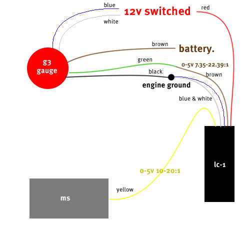
I CANNOT believe that this diagram didn't make it in here yet...
This is how it is setup on MY car. I'm sure others maybe be different. I also don't use the reset button or whatever it is.

The "engine ground" is at the ground point near the throttle body that the OP was pointing at in post #1.
The "12v switched" I stole from a thick gauge (12gauge maybe?) wire that I found under my dash that was hot when the key was switched on.
The brown (battery or 12v constant hot) goes straight to my alternator terminal using a fused wire. It's fused cause it goes through a hole in my firewall, and for that reason, it should be fused. I have stories about what happens when it isn't fused...but that's for a different time.
If you are running MS, make sure the signal wires (brown for gauge, and yellow to MS) are on 2 different settings which can be done with the LC-1 software. This is how people always post stuff like "my LC-1 and megasquirt aren't getting the same AFR's".
This is how it is setup on MY car. I'm sure others maybe be different. I also don't use the reset button or whatever it is.
The "engine ground" is at the ground point near the throttle body that the OP was pointing at in post #1.
The "12v switched" I stole from a thick gauge (12gauge maybe?) wire that I found under my dash that was hot when the key was switched on.
The brown (battery or 12v constant hot) goes straight to my alternator terminal using a fused wire. It's fused cause it goes through a hole in my firewall, and for that reason, it should be fused. I have stories about what happens when it isn't fused...but that's for a different time.
If you are running MS, make sure the signal wires (brown for gauge, and yellow to MS) are on 2 different settings which can be done with the LC-1 software. This is how people always post stuff like "my LC-1 and megasquirt aren't getting the same AFR's".
Reply
0
0


Thread
Thread Starter
Forum
Replies
Last Post
bigmackloud
Miata parts for sale/trade
19
01-08-2021 11:24 AM
JesseTheNoob
DIY Turbo Discussion
15
09-30-2015 02:44 PM


