
Hi performance boost control pwned


Thread Starter
Elite Member
Joined: Jul 2005
Posts: 6,420
Total Cats: 84
Being an electronics and controls nerd I wanted to see what it would take to have high performance boost control.
My wastegate can cracks open at 5 psi. Max boost is 15 psi.
Lots of people say you "can't have target boost more than 2x of your can cracking pressure". Baloney. You just have to know how to tune it.
I have an electronic (analog circuit) feedback loop monitoring (and setting) the pressure in the wastegate can (pressure sensor in line between solenoid and can). The main feedback loop (which targets manifold pressure), tells the electronic circuit how much can pressure it wants.
In feedback loop parlance, this is a "nested loop", where the inner loop is faster than the outer loop. Having a fast inner loop removes the "phase lag" aka delay due to the time it takes to fill and empty the wastegate can from the solenoid. Essentially the can pressure determines the position of the wastegate actuator. So the outer loop commands the actuator position.
The AEM ECU boost control feedback loop does PI control, sending a command (target can pressure) to the above circuit. The above circuit includes a "D" circuit in order to turn said PI into PID.
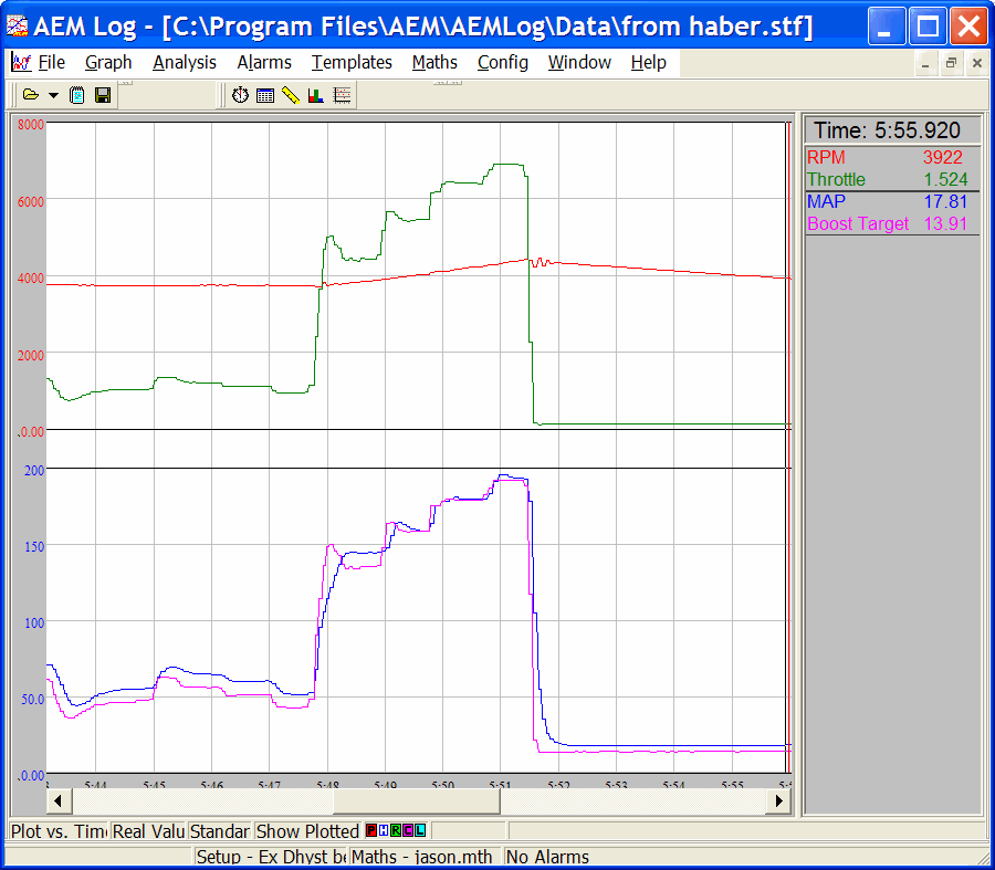
Here are two recent datalogs. Not they have different timescales.
Top half of each plot has RPM and TPS.
Bottom half shows target_MAP and actual MAP.
target_MAP is a function of TPS. So the target MAP has the same shape.
First datalog shows what happens when I put my foot in different positions.
Horizontal scale is 1 second per division:
Second datalog shows a bunch of on and off throttle to WOT.
Horizontal scale is 2 seconds per division. Worst case overshoot is 0.5 psi.

My wastegate can cracks open at 5 psi. Max boost is 15 psi.
Lots of people say you "can't have target boost more than 2x of your can cracking pressure". Baloney. You just have to know how to tune it.
I have an electronic (analog circuit) feedback loop monitoring (and setting) the pressure in the wastegate can (pressure sensor in line between solenoid and can). The main feedback loop (which targets manifold pressure), tells the electronic circuit how much can pressure it wants.
In feedback loop parlance, this is a "nested loop", where the inner loop is faster than the outer loop. Having a fast inner loop removes the "phase lag" aka delay due to the time it takes to fill and empty the wastegate can from the solenoid. Essentially the can pressure determines the position of the wastegate actuator. So the outer loop commands the actuator position.
The AEM ECU boost control feedback loop does PI control, sending a command (target can pressure) to the above circuit. The above circuit includes a "D" circuit in order to turn said PI into PID.
Here are two recent datalogs. Not they have different timescales.
Top half of each plot has RPM and TPS.
Bottom half shows target_MAP and actual MAP.
target_MAP is a function of TPS. So the target MAP has the same shape.
First datalog shows what happens when I put my foot in different positions.
Horizontal scale is 1 second per division:
Second datalog shows a bunch of on and off throttle to WOT.
Horizontal scale is 2 seconds per division. Worst case overshoot is 0.5 psi.
Last edited by JasonC SBB; Apr 9, 2012 at 04:55 PM.
Reply
 1
1

1


Thread Starter
Elite Member
Joined: Jul 2005
Posts: 6,420
Total Cats: 84
TurboTim, just make timing go lots retarded above the danger point. That'll prevent engine damage.
As for the circuit. I need to do longer term testing - check for stability, performance over time, degradation with parameter drift, etc.
I'm also thinking about some kind of overshoot arrester function in case the tables are set up wrong. And also an improved integrator algorithm that gets rid of "integrator windup" and the resulting overshoot.
The reasons I built this circuit... I noticed in bench testing with a pressure source, solenoid, and wastegate can, that the solenoid response to duty cycle is very nonlinear, and the actuator moves slowly to its final position when you put in a new duty cycle. And, the actuator "shivers" (vibrates) in time to the solenoid pulsing. Betcha you'd see the pulsing in the turbine inlet pressure as a result.
So my circuit will:
- get rid of the nonlinear effect of solenoid duty cycle vs. wastegate actuator position.
- get rid of the phase lag / delay from the time duty cycle changes, to the final position of the actuator, due to the time it takes to fill or empty the wastegate can (this is where the greatly improved response speed comes from)
- as a bonus if you change your solenoid you don't need to retune the tables, but perhaps only the 'D' term.
- it also runs the solenoid with variable frequency - at 50% duty cycle for example, it will run close to 30 Hz, because solenoids can run at higher frequency near 50% duty cycle. At more extreme duty cycles e.g. 10% or 90%, the frequency will go down to ~10 Hz. This feature reduces the "shivering" of the wastegate actuator.
Now instead of entering solenoid duty cycles in the AEM boost control table, I effectively enter target can pressure, (described by duty cycle LOL). The AEM effectively tells the circuit what can pressure it wants.
The AEM has:
- a 2D table to set up the boost control output duty cycle vs. boost target,
- a 3D one with RPM and MAP as axes. I use that to trim target can pressure vs. RPM. - Another 2D table for duty trim vs. boost error (a nonlinear 'P'),
- an 'I' gain term with limiting
- and of course a 3D table of boost target, with TPS and RPM as axes
As for building it for the masses ...
What does the MS2 have for lookup tables and PID?
If it is similar to the AEM but with 'D' built in, then the feedback loop will be in the MS, and the circuit just needs to have a duty cycle input and a pressure input from a tee to the wastegate can. If it has no 'D' then the circuit will need to implement the 'D', just like my prototype.
Reply
0
0
Thread Starter
Elite Member
Joined: Jul 2005
Posts: 6,420
Total Cats: 84
Can it do PID *and* have a TPS vs. target boost table?
If so, then my circuit can simply take a PWM "can pressure" command input, and a hose tee'd from the wastegate can.
Anyone want to play with a prototype?
Hustler:
EWG's are more linear and thus easier to tune without my circuit.
What my circuit can do for an EWG setup is perhaps make it faster and possibly make it even easier to tune for good response speed without oscillation.
What I don't know is, will it help appreciably enough?
Reply
0
0
Thread Starter
Elite Member
Joined: Jul 2005
Posts: 6,420
Total Cats: 84
BTW the most important improvement to boost control in my mind, is to have *adaptive* control. That is, you change something, you may start to get overshoot or under-boost, and it *learns* and adjusts. Just like the OEMs lol.
Adaptive control is a big topic which unfortunately I haven't had a lot of experience with.
Adaptive control is a big topic which unfortunately I haven't had a lot of experience with.
Last edited by JasonC SBB; Apr 10, 2012 at 12:15 PM.
Reply
0
0

i'd play.
I tested an EBC from a member here, remember brian007 or something like that? maybe it was loki007? i cant remember it was in like 2005 or 2006 or something.
it was called the AXIOM EBC. had a nipple and a lcd screen and two toggle buttons. you could enter in the boost target and then some senesitivty levels (probably d term) and it would just work, it actually worked well but nothing came of it.
had it controlling a GM boost solenoid.
Reply
0
0
Reply
0
0

Joined: Jun 2005
Posts: 19,338
Total Cats: 574
From: Fake Virginia
Reply
0
0
Thread Starter
Elite Member
Joined: Jul 2005
Posts: 6,420
Total Cats: 84
Judging from my experience pointing out the bug in the D of idle PID that GregG ran into, and watching the development of Gslender's code, they seem to be very reluctant to try anything not in their presumably very long "to do" list.
Reply
0
0

Thread
Thread Starter
Forum
Replies
Last Post
Zaphod
MEGAsquirt
47
Oct 26, 2018 11:00 PM


