
Na VSS signal and wiring


Thread Starter
Senior Member
iTrader: (10)
Joined: Aug 2007
Posts: 1,186
Total Cats: 4
From: Fredericton, NB
OK.
So after reading a few posts and doing some searches. I decided to put a wire on my 97s RSW screw on the back of the cluster and send it into the VSS(vehicle speed sensor) input on my ECU.
THIS DIDN'T WORK....regardless of what I read other places.
Is there another place where I can find it?? Does my stock gauge somehow take the mechanical signal and have a electronic output somewhere on it? Either way I would LOVE to have this kind of input.
It would make Boost feedback, Boost by gear, launch control ect... a walk in the park.
Reply
 0
0

0


Joined: Sep 2005
Posts: 34,402
Total Cats: 7,523
From: Chicago. (The less-murder part.)
The RSW terminal is just a switched closure to ground (there is literally a magnetic reed switch.)
Thus, it requires a pullup.
Did you provide a pullup?
Thus, it requires a pullup.
Did you provide a pullup?
Reply
0
0

Thread Starter
Senior Member
iTrader: (10)
Joined: Aug 2007
Posts: 1,186
Total Cats: 4
From: Fredericton, NB
...and once that turbo spools, that kitty is toast.
Reply
0
0
Joined: Sep 2005
Posts: 34,402
Total Cats: 7,523
From: Chicago. (The less-murder part.)
In its simplest form, a resistor connected between +5 and a signal wire.
You've got an ECU that's expecting a pulsed voltage input. And you've hooked it up to a device that does not provide a voltage output, it provides a switched closure to ground. So to make this circuit work, we place a resistor (1k usually) between a supply of power and the signal line in question.
Now, when the switch is open, the line will be energized to whatever voltage we're pulling it up to, and when the switch closes, that voltage drains to ground and the line goes to 0v. Thus, we achieve a pulsed voltage.
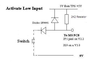
This method is quite common. Here's an example of a pullup applied in a launch-control situation- look at the "activate low" diagram, and ignore the diodes: http://msextra.com/doc/ms1extra/MS_E...l.htm#launchin
Actually, that's an attempt to control boost the same way they do with centrifugal superchargers, by placing a restriction inline with the compressor inlet. Kitty is precisely calibrated to achieve 12 psi at redline.
You've got an ECU that's expecting a pulsed voltage input. And you've hooked it up to a device that does not provide a voltage output, it provides a switched closure to ground. So to make this circuit work, we place a resistor (1k usually) between a supply of power and the signal line in question.
Now, when the switch is open, the line will be energized to whatever voltage we're pulling it up to, and when the switch closes, that voltage drains to ground and the line goes to 0v. Thus, we achieve a pulsed voltage.
This method is quite common. Here's an example of a pullup applied in a launch-control situation- look at the "activate low" diagram, and ignore the diodes: http://msextra.com/doc/ms1extra/MS_E...l.htm#launchin
...and once that turbo spools, that kitty is toast.
Reply
0
0
Thread Starter
Senior Member
iTrader: (10)
Joined: Aug 2007
Posts: 1,186
Total Cats: 4
From: Fredericton, NB
In its simplest form, a resistor connected between +5 and a signal wire.
You've got an ECU that's expecting a pulsed voltage input. And you've hooked it up to a device that does not provide a voltage output, it provides a switched closure to ground. So to make this circuit work, we place a resistor (1k usually) between a supply of power and the signal line in question.
You've got an ECU that's expecting a pulsed voltage input. And you've hooked it up to a device that does not provide a voltage output, it provides a switched closure to ground. So to make this circuit work, we place a resistor (1k usually) between a supply of power and the signal line in question.

I thought it would be a voltage output based on how fast I'm going, like most of all the other sensors in the car.
Your speaking of a switch/resistor combo and I don't understand the diagram.
What are the arrows with a line in front of them?? Why do I need my TPS signal at all? 0-volts = Ground yes?? Is the switch my existing wire or is that extra?
My IQ is falling by the second. I may try to find a friend who haz better edumacationz in this then me.
Reply
0
0
take a 2.2K resistor. Connect one end to VSS wire and the other to 5v. have a nice day.
The pull-up keeps the input high (5v) when the signal is not grounded. Otherwise, as your vss pulses to ground, it's not going back to voltage so the CPU can distigish anything from it. When the VSS signal grounds, the voltage drops from 5V to 0V. So now the CPU sees pulses.
Does that make sense?
The pull-up keeps the input high (5v) when the signal is not grounded. Otherwise, as your vss pulses to ground, it's not going back to voltage so the CPU can distigish anything from it. When the VSS signal grounds, the voltage drops from 5V to 0V. So now the CPU sees pulses.
Does that make sense?
Reply
0
0
Joined: Sep 2005
Posts: 34,402
Total Cats: 7,523
From: Chicago. (The less-murder part.)
Here's the simple version:
The VSS (on '90-'97 cars) is just a switch. When it's closed, it conducts to ground. When it's open, it does not. It opens and closes many times per second as the speedometer cable rotates.
Here are the two states of the VSS, which I have symbolized by drawing a SPST switch at the left side. In both of these drawings, I have added a pullup resistor at the top. At the right is the pin which feeds into the ECU (or the cruise control, or the A/T controller)
First, here is what it looks like when the VSS is open:
Voltage is coming in through the resistor, but it has nowhere to go, so the ECU sees +5v at its input.
Now, here is the VSS closed:
Voltage flows through the resistor, but it has a path to ground through the switch contacts. Thus, the voltage all drains out to ground, and the ECU sees 0v at its input.
If you imagine this system cycling back and forth between the two states at a high speed, the result (as seen by the ECU) will be a squarewave signal alternating between 0 and 5 volts.
The exact value of the resistor is not critical. You could use 1k, 2.2k, whatever you have lying around. 1k would be brown-black-red-(gold/silver), and 2.2k would be red-red-red-(gold/silver).
The key point is that without the resistor providing a pullup, the ECU will see 0v all the time, regardless of whether the VSS is open or closed. In the original design, the pullup resistor was inside the ECU (or the cruise control box or the A/T controller), however since you have none of those things, you need to supply the pullup yourself.
You don't.
I took that image from the MegaSquirt documentation. On that ECU, there is a pin labeled "TPS Vref" which is not specifically related to TPS, it's just a convenient source of +5v that it commonly used to provide a pullup for the TPS, as well as for whatever other external sensors need a +5 pullup. Your AEM probably provides a similar supply of external +5v. I don't know what pin on the AEM it is, but it should be going to pin 3I of the ECU harness (a light green / white wire) as this is how +5 is supplied to the TPS (as well as the EGR sensors and the TCM) in the factory harness.
Reply
0
0
Thread Starter
Senior Member
iTrader: (10)
Joined: Aug 2007
Posts: 1,186
Total Cats: 4
From: Fredericton, NB
Dear Joe,
THANK YOU
I am definitely understanding this quite a bit better.
To clarify a little more for dummies:
ECU = My AEM EMS +5V input
+5V = ? Not quite sure where this 5V will be coming from but its going through a resistor before being tied into the wire that goes between the ECU and
Switch = This is technically the VSS Output from the gauge cluster, the wire is already there.
So really, I need to find the input wire (Should be 3I as you've graciously told me) and splice another wire to it with a resistor to a +5V output (Should be one on the ecu somewhere)
Reply
0
0

Newb
Joined: Oct 2017
Posts: 33
Total Cats: 0
From: Seattle, WA
Going to necro since this thread is referenced and places and has a high search result, God forgive me for my sins.
If you were putting a digital dash in an early NA6, would you just replaced the VSS with a digital one and throw that into the MS? Or would you just relocate the current one, maybe trim it a bit and put it back in the circuit? Going to probably do this "mod" today so I can finally have speed in MS, but ultimately just going for a digital dash.
edit: In case it matters, currently on PNP2. One day I will upgrade.
Last edited by The Empty Guy; Sep 5, 2019 at 03:38 PM.
Reply
0
0

Thread
Thread Starter
Forum
Replies
Last Post


