When you click on links to various merchants on this site and make a purchase, this can result in this site earning a commission. Affiliate programs and affiliations include, but are not limited to, the eBay Partner Network.
I am creating a DIY CANbus gauge that will pull info from the CAN lines coming from a MS3x and display any useful information I wish. I am roughly following the idea of an instructables post I found here. The main difference being they created the user interface (ui) in the raw code and are only pulling info from the sensors that are already in place.
The general functionality of these gauge will be a single 1.28" round display that can fit in any of the three small gauge spots in the miata dash, I am choosing to use the coolant temp hole. The idea is to have multiple screens that can be switched through to see different info about the car. The sky is the limit here as MS can broadcast just about anything you can dream of. A simple push button will need to be mounted to get the gauge to switch screens and can be incorporated in any way the user would like.
Theres a few more "comfort" items on the list like soldering items and a 12v power source for testing.
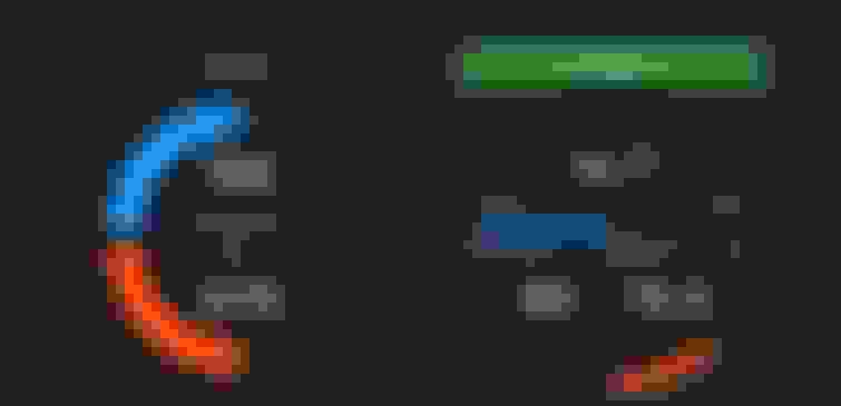
It is very possible you may have a lot of this on hand already, which is great you can lower your all-in cost that way. You will also need a means of soldering wires and of course a computer to code on, perferably a laptop as the board will become difficult to remove once installed. You can also find the .stl files for the mount linked in the instructables above. Below is a preview of the ui's two screens that I have created and will be using, but following posts will show how to use the software to create custom screens and code screen switching functionality into the file that will be flashed to the teensy.
edit: added ui version 2 to github with afr
The next post will mark the beginning of the project and the organization should be as follows...
Board and display soldering and wiring
Initial software setup and coding.
Display and Teensy Setup
Squareline Studio Tutorial for ui
Bench test display
Canbus and functionality backend coding
Connecting to cluster and CANbus
Last edited by Eli_Swer; 04-11-2024 at 02:40 PM.
Reason: Formatting
A really cool concept, I might tackle it if I didn't already have the Link unit.
You might consider making this all a shopping list on Amazon for easier 1-click, if you're smart you could even find a way to make a few pennies. Total came out to ~$150, but like you said there's a few places you could save some dollars.
Goooood idea, maybe I'll get on that especially since I already have an Amazon list for myself.
Yes, definitely lots of money to be saved with the adhesive, tape, bolts, wiring, etc. Good news is I got my ui uploaded to the teensy successfully and it showing on my lcd display. Screen switching and dimmer features both work too.
I should have those first three parts written up this evening, including pictures and videos!!
This is super neat looking. Cat given! Interested to see what it looks like installed. Are you planning to make the code opensource/available?
@curly I've been wanting to code one of these since the CANChecked I use has some bugs with the Link. I can't promise a date, but when I get something written I'll make it open source.
ninja edit: I just saw the bottom of your post. Ignore my question.
LETS BEGIN
1. HARDWARE SETUP
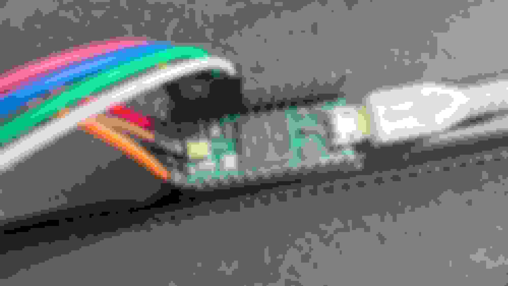
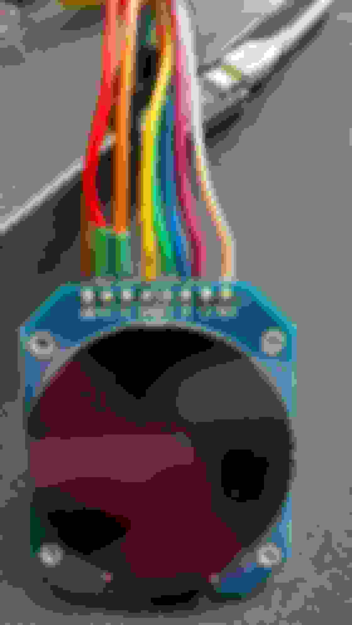
Getting the teensy and LCD wired up together is not too difficult. Take your time, get the pins soldered into the teensy and wires to the display. If you will be following the rest of this thread the wires from the LCD can be connected to the Teensy as follows.
SCL to pin 13
SDA to pin 11
RES to pin 8
DC to pin 9
CS to pin 10
BLK to pin 7
Later these pins will be defined in our setup file, if for whatever reason you are using a different board and want to/have to use different pins, you can define them differently in the UserSetup.h file that we will tinker with later.
2. Initial software setup and coding
You are going to need arduino IDE, which you can download from here. I am using version 2.3.2. You will also need to install "teensyduino" in order to load arduino sketches to your teensy. The link will walk you through the process. A. Display and Teensy setup
Getting the display setup involves two key components, getting a library downloaded and setting up our speficic setup in the UserSetup.h file. Open arduino IDE and on the left side there will be a tab for your library manager. Open it, search for tft_eSPI and install the latest version. Next you need to use your file manager to navigate to your arduino folder that was installed with the IDE, find the libraries folder within that, then the TFT_eSPI folder within that and locate the UserSetup.h file. Open it with something like notepad and get ready to make some small edits.
Scroll down to line 44 and comment out the "#define ILI9341_DRIVER" line (i.e. put '//' in front of it) This is a common driver used with arduino but not the one we are using! Also note your line numbers may vary slightly.
Now UNcomment the line for driver "GC9A01_DRIVER" on line 64
Lines 204 - 210 comment out all the pin definitions for the ILI9341 display
Lines 215 - 220 uncomment all the pin definitions for our GC9A01 display and set them to the pins we connected them to above...
MOSI (SDA) to 11
SCLK (SCL) to 13
CS to 10
DC to 9
RST (RES) to 8
BL (BLK) to 7
Make sure to save the file before closing and you are ready to run some tests. Get your pins from the display plugged into the teensy and teensy plugged into your computer. Open arduino IDE and make sure your teensy is being recognized by arduino via tha board and port drop down next to your verify, upload, and debugging buttons. Go to File > Examples > TFT_eSPI > Tools and diagnostics and run the colour test example. Make sure your display is working and give yourself a high five.
Pictures of the finished .h file for your reference.
I'm sold on the UI. What is the boot time at the moment?
After applying power to the teensy it takes just under 3 seconds for the display to power up. That is using usb power source. Might I have reason to believe that would be quicker with a 5v source directly to the Vin pin? Maybe. That will be the case upon final install. 12v source from car > 5v buck converter > Vin pin on teensy.
Not sure how quickly it might fetch values from the CANbus though.
Appreciate it! Thinking I'll have time tomorrow to share the UI design in squareline studio and explain how to use its different features. Also will be sharing a touch of coding in arduino for screen switching and dimming function. I am definitely going to be making a video for it, I would just end up with too many screenshots if I tried to do a write up. Also, I've got the actual ui file as well as the squareline project for my exact gauge up in a GitHub . Although, you can't download the singular ui file, upload it to a teensy, and get rolling, downloading the squareline project and following my instructions for export from squareline studio will create all the files you need to get the gauge up and going.
edit- To succesfully download the SquarelineStudio project from github, download both the .spj and .sll files then when you go to import the project into Squareline select the .spj and open it.
Here is the link to the youtube video I made walking through the ui design process quickly and some functionality coding for the gauge and a quick demo. You can test the dimming function by shorting the dim pin to a ground pin on the teensy to dim. Then you can short it to a 3.3v pin on the teensy to bring the brightness back up. NOTE: DO NOT APPLY MORE THAN 3.3V TO ANY PIN ON THE TEENSY. The screen switching you can test by touching a ground pin to the screen switch pin on the teensy. Everytime you ground that pin the screen will switch. Another note: the values at the end of the startup animation and beginning of the main loop are different on purpose, I have been testing that start animation and I am getting ready to integrate CANbus broadcasting. I made those values different to make sure the code was running as intended. There is also some commented out CAN fetching code in that startup animation function in the ui file, ignore it for now (as of 4/9/24).
Found this on Facebook, super cool project! I'm making something similar to display GM CAN messages for LS\LFX swapped cars. I bought a Pi since I didn't want to deal with designing a UI for a microcontroller, but it looks like squareline takes care of all the hard work.
Facebook, interesting. Mind sending the link lol, I didn't post anything there. Anyway yeah squareline is pretty easy but is not really being developed anymore. The library it uses (lvgl) stopped working with squareline a few software updates ago. It still works just fine but will fall out of date some day. Nextion displays and their software does something similar I think that may be EVEN easier.
Also as an update I nearly have my MS3x built. Been following brains instructions on trubokitty. Just need to finish the wiring harness, then I can get it in my car and iron out a base map. I will be messing with the CAN stuff after that!
I tried to go back and find it but I couldn't, I'm never able to find something again. Maybe someone linked to your thread since it was similar to what they were making. I'll have to look into Nextion, thanks for the recommendation. Looking forward to seeing it functinoal!
 04-05-2024, 11:28 AM


 9
9