
PNPAdurino AFM Eliminator


Joined: Sep 2005
Posts: 34,433
Total Cats: 7,549
From: Chicago. (The less-murder part.)
Sounds good.
In my experience, it is always best for analog sensors (or things feeding into analog inputs) to share the same signal ground as the ECU. That way, any noise present will be perceived equally by all devices and will not result in offsets.
In the '94 and later cars, Mazda took this to the extreme and actually ran the grounds for all of the analog sensors back into the ECU itself, whereupon they loop through it and go out to actual ground.
Most of the time I see people having calibration issues with wideband O2 sensors, for instance, it's because they did what they thought was "best" and ran a dedicated ground wire for the sensor controller separate from the ECU grounds. I expect you would encounter similar problems here if you start running separate ground lines for things that really need to share a common ground potential with the ECU, no matter whether that ground potential is the same as "true" ground or not.
Reply
 0
0

0

Thread Starter
Newb
Joined: Aug 2009
Posts: 35
Total Cats: 0
Reply
0
0

Elite Member
Joined: Jul 2005
Posts: 6,420
Total Cats: 84
My Arduino PWM into AFM-signal mimic works fine; I DVm'ed and scoped the output voltage at the AFM input terminals and it was fine.
The lesson is that the PWM output with a filter, done right, works fine.
The lesson is that the PWM output with a filter, done right, works fine.
Reply
0
0
Joined: Sep 2005
Posts: 34,433
Total Cats: 7,549
From: Chicago. (The less-murder part.)
What sort of time-constant did you end up with on that?
Reply
0
0

Newb
Joined: Apr 2010
Posts: 10
Total Cats: 0
so if i understand this correctly in order for us to limit the amount of unnecessary I/O usage, we are going to take 5v hot Source from the stock ECU using 1 I/O pin from the AFM harness. followed by grounding the PNPAdruno directly to the Stock ECU. by dong that we can take the guess work out of grounding issues. also this would mean that the aftermarket Map sensor will be needed to be grounded at the PNPAdruno level.
sounds simple enough. besides we are going to have an even more headache needing to splice into the oem harness to get an auxiliary source rpm input from TDC sensor and CKP sensor from the CAS.
and this signal source has to be ran in parallel. someone has already written a code for rpm source already right? (those who don't know it'll have to be run parallel or a 12-1 wheel will need to be retrofitted with a sensor which will cost more money and a new code will need to created in it's place).
anyways this sounds good so far... now about those tables...
Reply
0
0
Elite Member
Joined: Jul 2005
Posts: 6,420
Total Cats: 84
Writing code from stock crank or cam signals to generate RPM is easy. (no you don't need both)
As for the AFM-mimic voltage output, I used a curve fit equation, not a table. I posted the equation in another thread.
As for the AFM-mimic voltage output, I used a curve fit equation, not a table. I posted the equation in another thread.
Reply
0
0
Joined: Sep 2005
Posts: 34,433
Total Cats: 7,549
From: Chicago. (The less-murder part.)
we are going to take 5v hot Source from the stock ECU using 1 I/O pin from the AFM harness. followed by grounding the PNPAdruno directly to the Stock ECU. by dong that we can take the guess work out of grounding issues. also this would mean that the aftermarket Map sensor will be needed to be grounded at the PNPAdruno level.
Fundamentally, this all sounds kosher.
we are going to have an even more headache needing to splice into the oem harness to get an auxiliary source rpm input from TDC sensor and CKP sensor from the CAS.
All you need is the CKP (Ne) signal, which is a white wire at pin 2E of the ECU, or you're under the hood, you can pick it up right at the cam sensor. This will give you a 0-5v squarewave (the stock ECU provides the pullup) with two pulses per crank revolution.
Reply
0
0
Newb
Joined: Apr 2010
Posts: 10
Total Cats: 0
anyways it's plan on going in there.. although i plan on mounting the Map Sensor near the engine bay and I'm planning on wiring the map outside of the ecu as i think most people here want to run a tee. but that's just me.
One vampire tap is a headache?
All you need is the CKP (Ne) signal, which is a white wire at pin 2E of the ECU, or you're under the hood, you can pick it up right at the cam sensor. This will give you a 0-5v squarewave (the stock ECU provides the pullup) with two pulses per crank revolution.
All you need is the CKP (Ne) signal, which is a white wire at pin 2E of the ECU, or you're under the hood, you can pick it up right at the cam sensor. This will give you a 0-5v squarewave (the stock ECU provides the pullup) with two pulses per crank revolution.
Reply
0
0

Senior Member

Joined: Aug 2010
Posts: 613
Total Cats: 3
From: Maumelle, AR
My 2c, Just get an ms3... Then you'll have your ms2 as a spare, and we can concentrate more on making the ms-can-display project extra badass  I just gotta find time to code, and we just had our 3rd child last night, so its going to be difficult in the short term :(
But, that said, this is a pretty cool project, there's a lotta AFM cars out there.
I just gotta find time to code, and we just had our 3rd child last night, so its going to be difficult in the short term :(But, that said, this is a pretty cool project, there's a lotta AFM cars out there.
Reply
0
0
Joined: Sep 2005
Posts: 34,433
Total Cats: 7,549
From: Chicago. (The less-murder part.)
Reply
0
0
Newb
Joined: Apr 2010
Posts: 10
Total Cats: 0
hey jason sbb
is there anyway for you to post the Code of your afm mimic for your adruino.
i've looked and looked and i can't seem to find your code other then the one bloodline posted up in the other thead about the adruino standalone
i've studied as much as i can about coding these past few weeks (all this time as this thread became somewhat idle) and i learned that it's better to let the expert do the software side of things.
i got a buddy who codes for Microsoft in Seattle. Owes me a favor, doesn't know a lick of thing about cars. but I'm sure i can explain the concept of a 1.6 CAS.
anyway you could repost that equation curve of yours? I'd like to save some time instead of attempting to get it written from the ground up. so at least it's modified where it can use a 1.6 cam and rid of the excess outlet code.
Reply
0
0
Elite Member
Joined: Jul 2005
Posts: 6,420
Total Cats: 84
from https://www.miataturbo.net/showpost....9&postcount=50
AFMvoltage =
1.746
+ 1.639 * RPMscaled
+ 0.6576 * MAPscaled
- 0.8774 * RPMscaled^2
+ 1.465 * RPMscaled*MAPscaled
Where RPMscaled = RPM / 7000, clipped to a max of 1
and MAPscaled = MAP / 100, clipped to a max of 1
This fits the data I gathered from my 2000 with ~1% RMS error.
AFMvoltage =
1.746
+ 1.639 * RPMscaled
+ 0.6576 * MAPscaled
- 0.8774 * RPMscaled^2
+ 1.465 * RPMscaled*MAPscaled
Where RPMscaled = RPM / 7000, clipped to a max of 1
and MAPscaled = MAP / 100, clipped to a max of 1
This fits the data I gathered from my 2000 with ~1% RMS error.
Last edited by JasonC SBB; Jul 22, 2011 at 11:39 AM.
Reply
0
0
Elite Member
Joined: Jul 2005
Posts: 6,420
Total Cats: 84
Code. Spacing formatting is lost so I'll also attach the file.
Note this also generates an NB style crank trigger signal from a TSE 12+1 trigger wheel.
-------------------------------------------------------------------------------------------------
// this is to generate miata NB crank trigger pattern, 80 and 10 BTDC pulses
// and generates curve fitted MAF signal from 2.5bar Motorola MAP sensor and RPM
//from 12-1 wheel with missing tooth at 30* ATDC
//toothPeriod with 12 tooth wheel at 9000 RPM is 555u
// with 18 us per degree
// at 7200 RPM it's 694 us between normal teeth, with 23 us per degree
// at 100 RPM it's 100 ms during the missing tooth
const int CKPin_Pin = 2;
const int MAFoutPin = 3;
const int CKPout_Pin = 4;
const int CKPPinInterruptNo = 0; // this is for pin 2
const int LED_Pin = 13;
const int MAPinPin = 0;
volatile byte ATooth=0; //tooth counter, counts 0 to 12; 12th is early, extra tooth, then resets to 0
volatile unsigned long toothPeriod=0; // time between teeth
volatile unsigned long lastToothPeriod=0;
volatile unsigned long normalToothPeriod=10; // time between non-missing teeth // initialize to a large number fro startup
volatile unsigned long toothTime=0; // system micros() time when tooth passed (rising edge)
volatile unsigned long lastToothTime=0; // system micros() time when previous tooth passed
boolean LEDstate=HIGH; // temp
//boolean outputState=HIGH;
void setup() { // run once in Arduino upon reset or powerup
pinMode(CKPin_Pin, INPUT);
pinMode(CKPout_Pin, OUTPUT);
pinMode(MAFoutPin, OUTPUT);
pinMode(LED_Pin, OUTPUT);
pinMode(MAPinPin, INPUT);
attachInterrupt(CKPPinInterruptNo, edgedetected, RISING);
digitalWrite(CKPout_Pin, HIGH);
// Serial.begin(9600); // temp
}
void edgedetected() { // interrupt routine on rising edge detected on CKP input
lastToothTime = toothTime;
toothTime = micros();
lastToothPeriod = toothPeriod;
toothPeriod = toothTime - lastToothTime;
if (toothPeriod < ((lastToothPeriod)*6/10)) { // early (extra) tooth detected // try .33 and .7
toggleLED(); //temp
ATooth = 12; // force to 12; it will be 12 anyway if it's in sync
// toothTime = lastToothTime; // undo toothTime assignment
// toggleLED();
; //
}
else { // regular tooth gap, or just after extra tooth
ATooth++;
if( (ATooth) > 12 ) {
ATooth = 0; // when it reaches 13, cycle around to 0;
normalToothPeriod = toothPeriod + lastToothPeriod;
} else normalToothPeriod = toothPeriod; // we just passed a normal tooth gap
}
/* Serial.print(ATooth,DEC); // temp
Serial.print(" ");
Serial.print(normalToothPeriod,DEC);
Serial.print(" ");
Serial.println(toothPeriod,DEC); // temp */
// if ( ATooth == 10 ) {
// Serial.println("it's 10");
// digitalWrite(CKPout_Pin, LOW); // temp
// }
// if ( ATooth == 11 ) {
// Serial.println("it's 11");
// digitalWrite(CKPout_Pin, HIGH); // temp SOMEHOW this one doesn't work, it doesn't toggle
// }
}
int MAP;
unsigned long temptoothPeriod;
unsigned long MAPscaled;
unsigned long RPMscaled;
unsigned long MAF;
// re: doMAF() which calculates MAF voltage.
// MAP input (analogRead()) reads 0-1023 for 0-5V. Freescale 2.5bar MAP sensor equation is Vo = 5*MAP/250 - 0.2
// or analogread result = 1023*(MAP/250)-41
// large equation below is written for MAPscaled and RPMscaled to be 4095 (12 bits) full scale
// returns MAF value which is 0-255, written to PWM output, which produces 0-5V
// orig curve fit eqn is:
// MAFvoltage = 1.746 + 1.639 * RPMscaled + 0.6576 * MAPscaled - 0.8774 * RPMscaled^2 + 1.465 * RPMscaled*MAPscaled
// where MAF ranges from 2~4.6V (when MAP is 20~100 kpa and RPM is 500-7000), and RPMscaled = RPM/7000 and MAPscaled=MAP/100
// the large equation has been carefully ordered to maximize precision without overflow
// eval of all equations (not including analogRead and analogWrite) takes ~100 us.
// If I use shift right instead of divide/2^n is saves about 20 us
// analogRead() adds another 100 us and analogwrite() perhaps 20 us.
void doMAF() {
MAP=analogRead(MAPinPin);
temptoothPeriod = constrain(normalToothPeriod,715,10000); // limit RPM range for use in equation, to 500-7000 rpm
MAP = constrain(MAP,41,367); // limit MAP to 20~100 kPa
RPMscaled = 2925714 / temptoothPeriod; // 7000 RPM is 1023
MAPscaled = ((unsigned long)MAP+41)*10; // 100 kPa is 1023
MAF = (1430 + 1342*RPMscaled/4096 + 539*MAPscaled/4096 - RPMscaled*RPMscaled/4096*719/4096 + MAPscaled*RPMscaled/4096*1200/4096)/16;
analogWrite(MAFoutPin, MAF); // default settings is ~490 Hz PWM, accepts values 0-255
// toggleoutput();
}
unsigned long itIsTime=0;
unsigned long tempToothTime=0;
boolean pulsed80_na=false; // flag if 80* BTDC pulse is has already been outputted
boolean pulsed10_na=false; // flag for 10* BTDC
boolean MAFout_na=false; // flag if doMAF() has been executed already
void loop() { // main Arduino loop
if( ATooth==1 || ATooth==7 ) { // 80* BTDC pulse, begins 17* after tooth 1 and 7, 3* wide
if(!pulsed80_na) {
tempToothTime = toothTime; // store toothTime in temp var bec toothTime is volatile
itIsTime = normalToothPeriod *17/30 + tempToothTime; // calculate when 17* later is
while( micros() < itIsTime); // do nothing until 17* have passed; micros() returns how many microseconds elapsed since powerup
digitalWrite(CKPout_Pin, LOW);
itIsTime = itIsTime + normalToothPeriod/10; // 3* later
while( micros() < itIsTime); // do nothing for 3*
digitalWrite(CKPout_Pin, HIGH);
pulsed80_na=true;
}
} else { // not tooth 1 or 7
pulsed80_na=false;
}
if( ATooth==3 || ATooth==9 ) { // 10* BTDC pulse
if(!pulsed10_na) { // 10* BTDC pulse, begins 27* after tooth 3 and 9, 3* wide
tempToothTime = toothTime; // store toothTime in temp var bec toothTime is volatile
itIsTime = normalToothPeriod *27/30 + tempToothTime; // calc time when 27* is; normal tooth period is 30*//
// note: this will fail if it wraps around (70 minutes)
// if( itIsTime < micros() ) { // it wrapped around
// while(itIsTime < micros() ); // wait til micros() wraps around too
// }
while( micros() < itIsTime);
//while( micros() < itIsTime && (ATooth ==3 || ATooth==9)) ; //do nothing until required 27* time passes or tooth comes early
// note if next ATooth arrives we'll be >= 3* behind but that's OK
digitalWrite(CKPout_Pin, LOW);
// if( ATooth==3 || ATooth==9) { // tooth didn't increment early
//itIsTime = toothPeriod + tempToothTime;
// } else { // Atooth came early
itIsTime = itIsTime + normalToothPeriod/10; // 3*
//}
while( micros() < itIsTime);
digitalWrite(CKPout_Pin, HIGH);
// toggleoutput();
pulsed10_na=true;
}
} else { // not tooth 3 nor 9
pulsed10_na=false;
}
if( ATooth == 1) { // just don't do it before or after extra tooth , let's calc MAF output .... once very rev; may want to add qualifier for doing it only every 100 ms or so
if(!MAFout_na) {
doMAF();
MAFout_na=true;
}
} else { // not tooth 10
MAFout_na=false;
}
}
Reply
0
0
Thread Starter
Newb
Joined: Aug 2009
Posts: 35
Total Cats: 0
Could anyone with an AFM (89 - 93 flappy potentiometer style) help me out with some ballpark measurements of the connector?

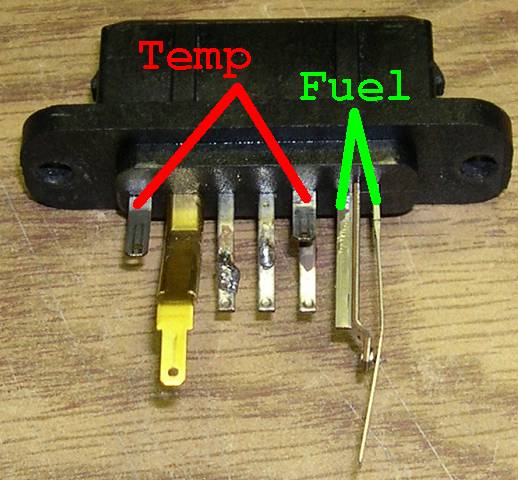

I want to pick up a little hobby box for this project whilst I am still in Germany, but I don't have an AFM connector / car to measure for a size reference.
I want to pick up a little hobby box for this project whilst I am still in Germany, but I don't have an AFM connector / car to measure for a size reference.
Reply
0
0

Thread
Thread Starter
Forum
Replies
Last Post
bigmackloud
Miata parts for sale/trade
19
Jan 8, 2021 11:24 AM


