
VVT box woes.... Please Help


Thread Starter
Junior Member
iTrader: (2)
Joined: Jan 2011
Posts: 258
Total Cats: 4
From: Columbus Ohio
So I'm back again with more issues on this -
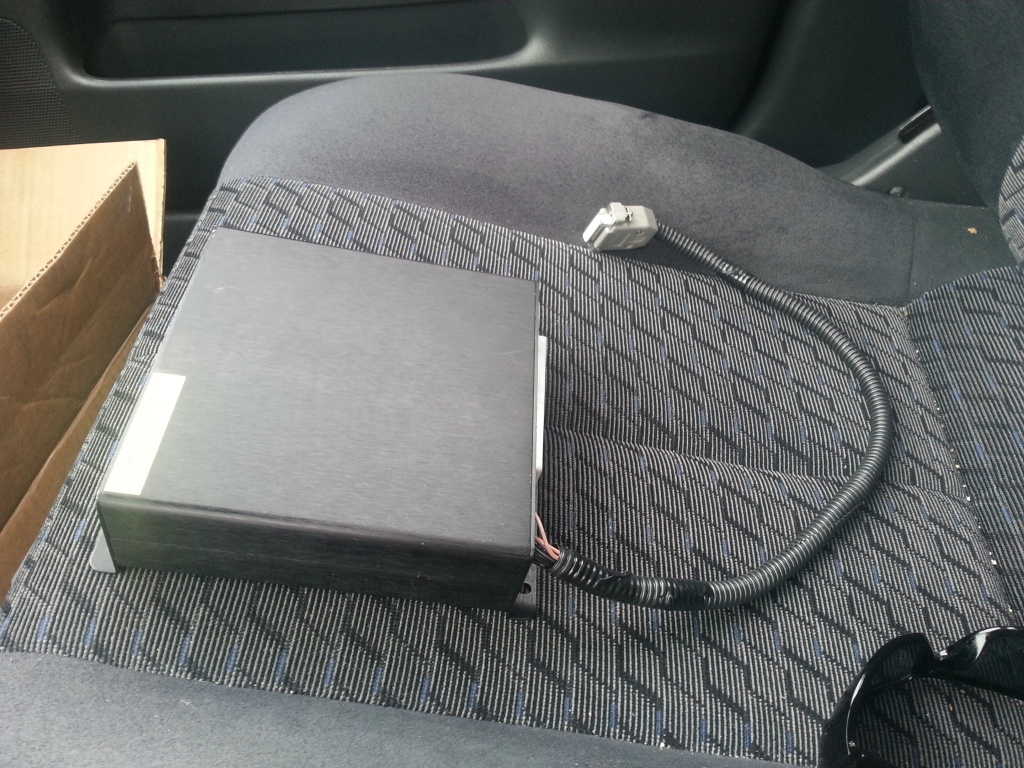
I purchased a brand new VVT box from DIY this week and I'm still in the same boat -
Attempts to start look exactly the same on the screen/logs as before -
I"m seeing the box, I'm loading the base map, and I"m attempting to start with jumpers off the ms2 board
Box has everything it's supposed to and is powered on -
NO GO
So if anyone has suggestions on potential next steps for troubleshooting I would very much appreciate it....
Quick question - The car ran smoothly on the stock ecu before all of this
If the vvt solenoid was bad and I was running no vvt on the stock ecu would I know?
Would I have a DTC/LIght?
Would it run like crap?
Also are there any other settings in tuner studio I need to address here in order to make the vvt box function? Vvt box is powered thru ms2 but I'm doing all comm w it independently
Please help....
Thanks to anyone, Chris
Edit
Another quick note -
Under the output trigger type option I have attempted to use all 4 settings
With none the car will not start at all
With 91-97 na the car will not start at all
With 01-05 passthrough the car sound like its going to start but sputter and make some really nasty noises
With 01-05 inverted the car will start and idle like crap - the target advance will read what's in the table but the cam advance will read -33 to-34
More troubleshooting
Using this guide -
VVTuner Standalone Programmable VVT Controller Troubleshooting Guide
on 01-05 passthrough attempted some of the troubleshooting steps
after looking at the log i've attached i thought i might need to go down the path of the 2nd problem listed
so i tried p=20 i=15 d=0
and i did that datalog
i changed the duty cycle limits to max 100% and min 10%
still same results..
some big questions i'm left with here -
what settings is output trigger type supposed to be on??? there are 2 for nb2? is this dependent on wiring in ms2?
i can only assume the crankshaft trigger wheel is correct - otherwise wouldn't ms fail to run the car correctly w/out vvt
can someone point me in the right direction of each pin and what it needs to be connected to on the board in order for this thing to work correctly? i have the plug pinout for the vvt box
i stopped by the local dealer today and discovered a new solenoid (vvt) is $310
i have a hard time buying that given the car ran before i installed ms w/ no issues
Last edited by cpolly69; Jul 15, 2013 at 05:52 PM.
Reply
 0
0

0


If you are splitting the signal there is some things to play with regarding pullup/down resistors (I skipped that part).
Make a small harness to enable running the MS without the VVTuner, it helps keep the mind sane when you can troubleshoot in steps.
Regarding the absurd advance, check the OCV limits, especially the lower limit (was set to 30% for me). A too high lower limit will advance the cam with rising oil pressure regardless what target the tables have.
No, I have not read the whole thread, just wanted to share some of my headaches with a similar setup.
Reply
1
1
Thread Starter
Junior Member
iTrader: (2)
Joined: Jan 2011
Posts: 258
Total Cats: 4
From: Columbus Ohio
aballoonflies from this thread
https://www.miataturbo.net/ms-labs-m...oup-buy-50791/
s/n: 10019
thanks
Reply
0
0
Thread Starter
Junior Member
iTrader: (2)
Joined: Jan 2011
Posts: 258
Total Cats: 4
From: Columbus Ohio
With the cam/crank signals going through the VVTuner to the MS the setting should be NB inverted.
If you are splitting the signal there is some things to play with regarding pullup/down resistors (I skipped that part).
Make a small harness to enable running the MS without the VVTuner, it helps keep the mind sane when you can troubleshoot in steps.
Regarding the absurd advance, check the OCV limits, especially the lower limit (was set to 30% for me). A too high lower limit will advance the cam with rising oil pressure regardless what target the tables have.
No, I have not read the whole thread, just wanted to share some of my headaches with a similar setup.
i'm hoping i won't have to bypass the ms all together, but i was thinking of it at this point
according to this i've got 15 pins on the connector
looks like i need wiring to the camshaft pos sensor
the crankshaft pos sensor
several grounds switched ign and a few other things including the actual vvt solenoid
i'm a bit confused on the diagram for a few other things an not sure what to do about the stuff refereed to inside ms
any chance you could give me the laymen's breakdown to where each wire needs to go 1-15?
i mean i don't need pics or anything, just description
Reply
0
0
With the VVTuner in place the Cam and Crank sensor signals enter my DIYPNP by the stock harness and are connected directly to the DB15 for the VVTuner with no other connection in the DIYPNP.
The signals back from the VVTuner in the DB15 are then connected to the appropriate place on the DIYPNP board.
The power and grounds are close to obvious.
Reply
1
1

this was origionally built for user
aballoonflies from this thread
https://www.miataturbo.net/ms-labs-m...oup-buy-50791/
s/n: 10019
thanks
aballoonflies from this thread
https://www.miataturbo.net/ms-labs-m...oup-buy-50791/
s/n: 10019
thanks
you probably have to change your pull-up on the crank/cam like everyone else with a DIYPNP and VVTuner.
Reply
1
1
Thread Starter
Junior Member
iTrader: (2)
Joined: Jan 2011
Posts: 258
Total Cats: 4
From: Columbus Ohio
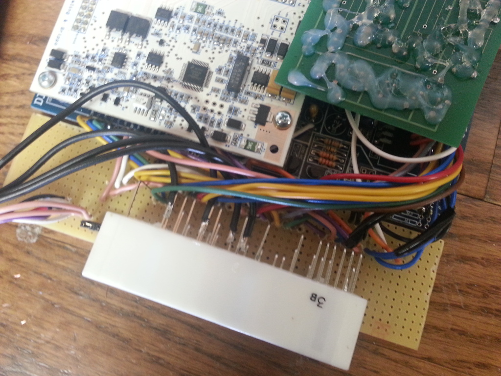
edit
well i think aaronc7 has found the resistor i need to change from 12v to 5v pictured here

it's opt 0 and apparently another user gorillazfan was having the same issue as me and figured it out...
hoping rev can weigh in on thoughts here...
Last edited by cpolly69; Jul 18, 2013 at 02:12 AM.
Reply
0
0

Yeah, I found another thread from April/May time frame where 'gorillazfan' was having the exact same issues as Chris. He ended up changing OPTO+ to 5v from 12v and it worked like a charm.
Reply
0
0
Thread Starter
Junior Member
iTrader: (2)
Joined: Jan 2011
Posts: 258
Total Cats: 4
From: Columbus Ohio
OK so i changed the resistor and still fail city lol
I when i turn the ocv min limits down to 0 i can get the car to idle really crappy on inverted
This is basically the same results I've had all along
But
I've got some more data to look at here -
The first thing that smacks me in the face is this
Check out the rpm on the vvt tuner software vs ts
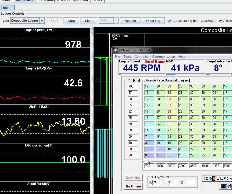
Also I've attached a normal datalog and a composite datalog
So I guess the way the vvt box sees rpm is wacked? How do I go about fixing that.....
Reply
0
0
We really gotta figure out how your crap is actually wired up. You were told to remove the 2 jumpers on the MS board if VVTuner installed, or install them with VVTuner uninstalled. We're not even sure if the cam/crank signal is getting sent to the VVTuner only, or if they are being split and being sent to VVTuner and MS independently.
Your composite log- the crank signal looks a bit wonky, at least they do not look like gorillazfan's. Actually it looks 'inverted', so maybe it's safe to assume that yours is wired up such that the sensors are going to the VVTuner only, then being forwarded onto MS. That still doesn't explain why your VVTuner is getting a weird RPM reading and MS seems to be getting RPM fine.
I say try wiring it up like gorillaz- split the cam/crank signals and send them to VVTuner and MS separately....then mess with the pullups as needed (you may already be squared away there).
Reply
0
0
Thread Starter
Junior Member
iTrader: (2)
Joined: Jan 2011
Posts: 258
Total Cats: 4
From: Columbus Ohio
We've been working on this the past few hours, think we might be getting close. We split the cam/crank signals to both the VVTuner and MS separately. Got a good rpm readout in VVTuner, but now MS is always showing 0 RPM. Did a composite log, and the cam signal looks normal, but crank signal is blank. I'm guessing this means we need to change the pullup on the crank/OPTO+? Any other thoughts? Getting very frustrated trying to get this thing to work.
Attached is last cranking composite log.
Attached is last cranking composite log.
Reply
0
0
We switched it over to 5v and got this result which is confusing us even more-- everything I have found on here said that switching from 12 TO 5v fixed the issue when sharing the sensor. Perhaps a bad wire connection..... ugh.
Initially we had the cam/crank signals backwards going to the MS (oops), with both pull ups to set 5v. You could see each signal fine in composite log, they were just backwards. So I switched the wires and now we're running into this issue.
Initially we had the cam/crank signals backwards going to the MS (oops), with both pull ups to set 5v. You could see each signal fine in composite log, they were just backwards. So I switched the wires and now we're running into this issue.
Reply
0
0
Thread Starter
Junior Member
iTrader: (2)
Joined: Jan 2011
Posts: 258
Total Cats: 4
From: Columbus Ohio
so after 6 long hours of messing with this thing we got it running
several combos of stuff happened before we actually got it right
here's some highlights -
vvt box is getting cam and crank sig straight from the factory wiring
the colors of the wires were reversed for cam and crank (sig) from the board to the plug - we traced them back to opt 0 and vr2 according to what diy's site said for what they should be
when i first opened up the vvt plug i discovered there was only one wire going to the ocv - i added the 2nd wire to the plug and both of those wires are also directly wired into the stock wiring
the jumpers are on and i have just 4 wires into the stock wiring
opt 0 is on 5v
it works
Reply
0
0
Welp, at the end of the day it was really just some confusion/false assumptions we made early on about how the ECU routed some of the signals around that caused our issues....glad it's all sorted out now.
Basically we followed the picture that Braineack posted and it worked great, with 5v pullup for OPTO+.
Basically we followed the picture that Braineack posted and it worked great, with 5v pullup for OPTO+.
Reply
0
0
Thread Starter
Junior Member
iTrader: (2)
Joined: Jan 2011
Posts: 258
Total Cats: 4
From: Columbus Ohio
So over the last few days I had intermittent issues with seeing correct rpm on both vvt box and ms at the same time. I figured it had to be a connection issue with either a stupid butt end connector or one of the clip on thing we used splice into the factory harness. I went over the wiring 3 or 4 times trying to check it all and couldn't get it to work every time I started it up.
So I figured the inside of the plug on the ms was the same as the actual factory harness itself -
So i started to pull everything out and I drew some fancy diagrams -
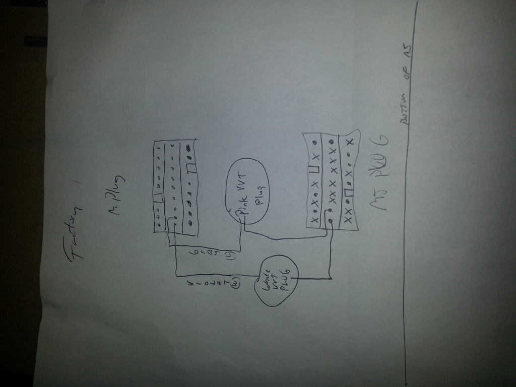
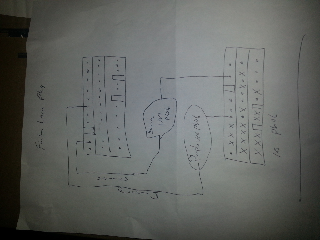
Then I asked a buddy of mine that actually know wtf he's doing when it comes to soldering to add the 4 wires I needed for cam sig, crank sig, ocv + and ocv - on the inside of the plug
Then he soldered those wires back to the vvt box plug and we closed the whole thing back up - put a new wire loom on it and I'm back to having an actual pnp setup again -
I installed it again and it runs like a champ -
Drove around for a while tonight and let VE analyzer do it's thing to correct AFR now that I'm running VVT
If anyone has any slightly more aggressive base maps for VVT on ms2 (NA)I'd love to give them a try...
So I figured the inside of the plug on the ms was the same as the actual factory harness itself -
So i started to pull everything out and I drew some fancy diagrams -


Then I asked a buddy of mine that actually know wtf he's doing when it comes to soldering to add the 4 wires I needed for cam sig, crank sig, ocv + and ocv - on the inside of the plug

Then he soldered those wires back to the vvt box plug and we closed the whole thing back up - put a new wire loom on it and I'm back to having an actual pnp setup again -

I installed it again and it runs like a champ -
Drove around for a while tonight and let VE analyzer do it's thing to correct AFR now that I'm running VVT
If anyone has any slightly more aggressive base maps for VVT on ms2 (NA)I'd love to give them a try...
Reply
0
0


