When you click on links to various merchants on this site and make a purchase, this can result in this site earning a commission. Affiliate programs and affiliations include, but are not limited to, the eBay Partner Network.
The whole thing originated HERE, with me asking some questions about venting the crankcase..
Then @sixshooter pretty much showed me the way. I was convinced.
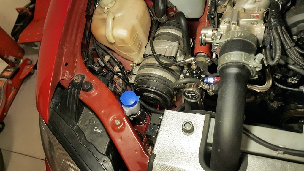
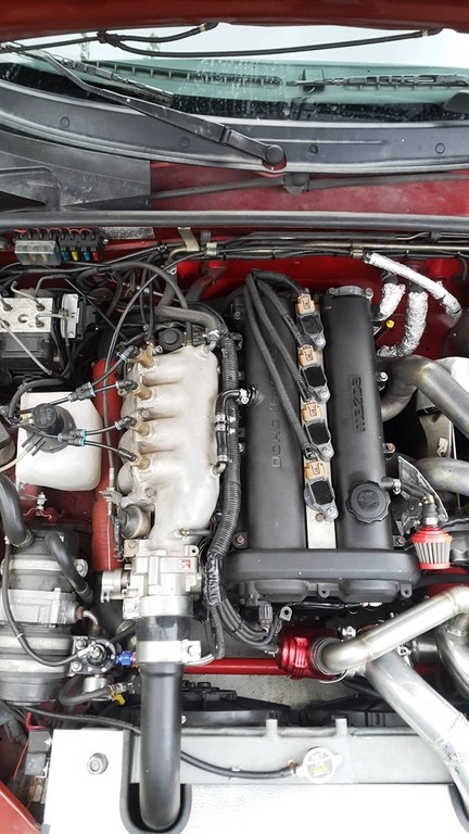
One problem: My engine bay is crowded already. Like Walmart on Black Friday crowded.
There is no room for a catch can.
I decided to relocate the windshield washer bottle next to the intake manifold and fab a breather tank there.
The washer bottle could live inside the front bumper, under the right headlight.
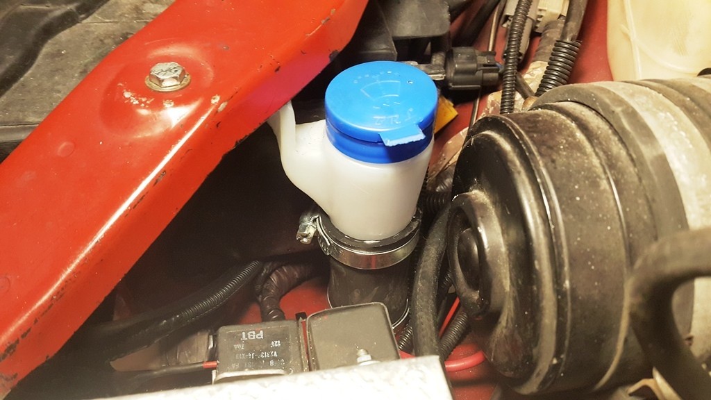
So, I started with the washer bottle...
I begun by obtaining a washer bottle made for a Fiat Linea. They are manufactured here, parts are plenty and cheap...
Here is what I bought:
I knew I would have to perform some surgery...
I probably supported the thing more than necessary, but I'm fairly confident it will not fly out of the car on the freeway...
Since it would be damn inconvenient to get under the car to fill the bottle, I went ahead and made a nifty fiiller neck next to the headlight, too.
A new water line and extending the power and ground wires (in proper cable sheathing) finished that part of the catch can project.
(Increased water capacity was a bonus - also, this Linea pump has much more power, too)
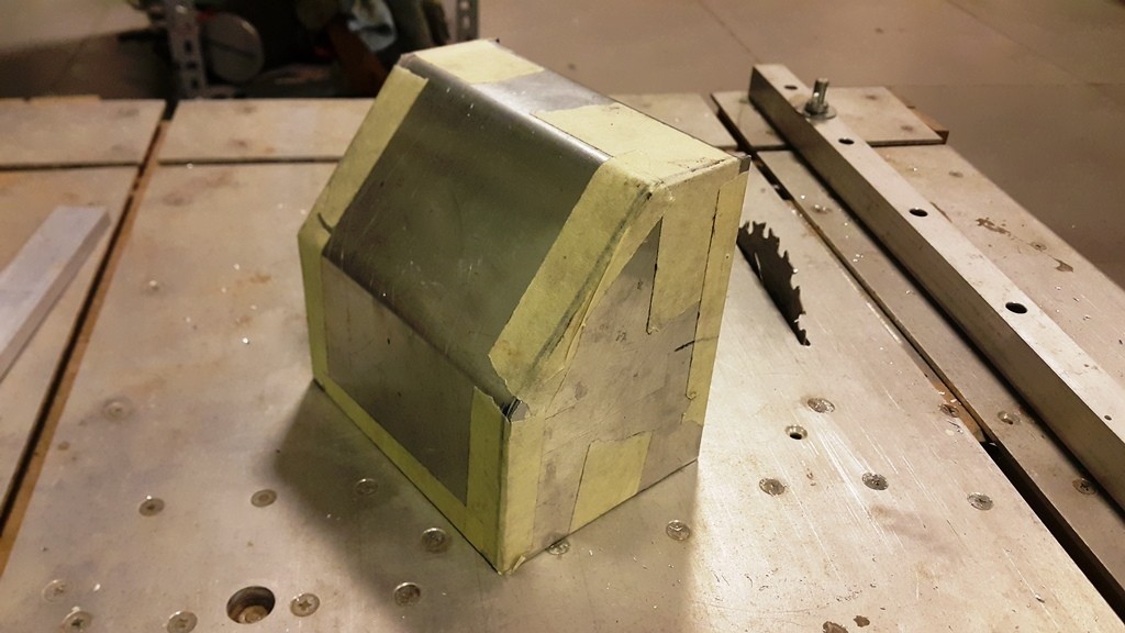
On to the actual catch can / breather tank thing...
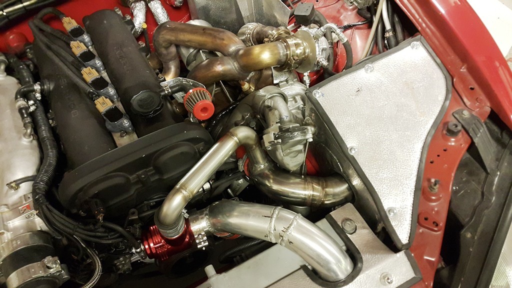
First and foremost, I would use hard lines.
* If done correctly, a hard line setup looks like it belongs there.
* It will raise fewer eyebrows come inspection time.
* Looks pretty cool, and
* I had promised myself I would do it this way when the time came.
Made a couple calls and found someone who knows someone who has a pretty good tube bender.
The only catch was it was for 16 mm tubing.
Which meant my lines would not be 5/8 ID (16 mm). They are 9/16 ID (14 mm) instead.
Steve, will this be a problem?
I have no choke points, ID is uniform all the way to the breather tank.
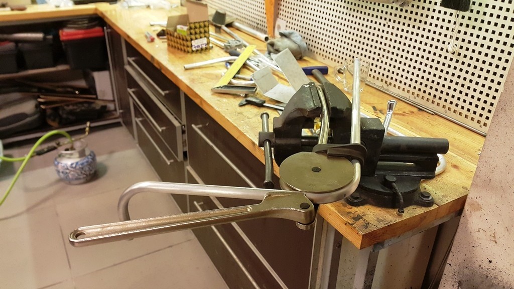
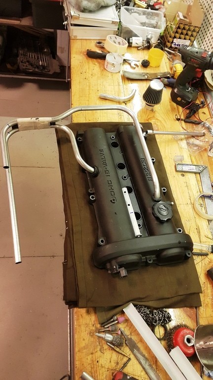
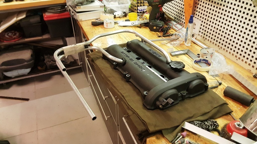
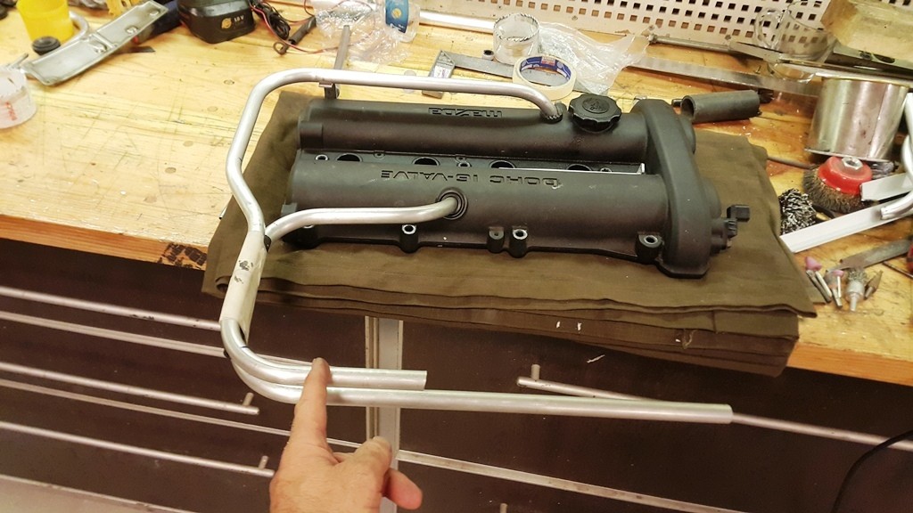
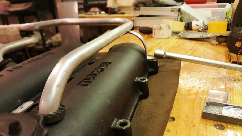
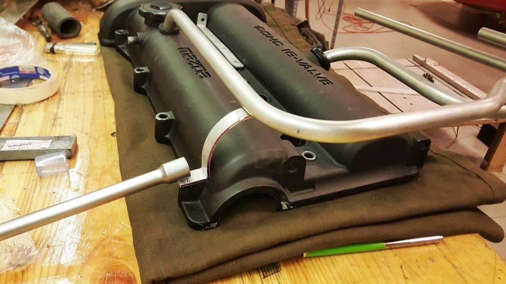
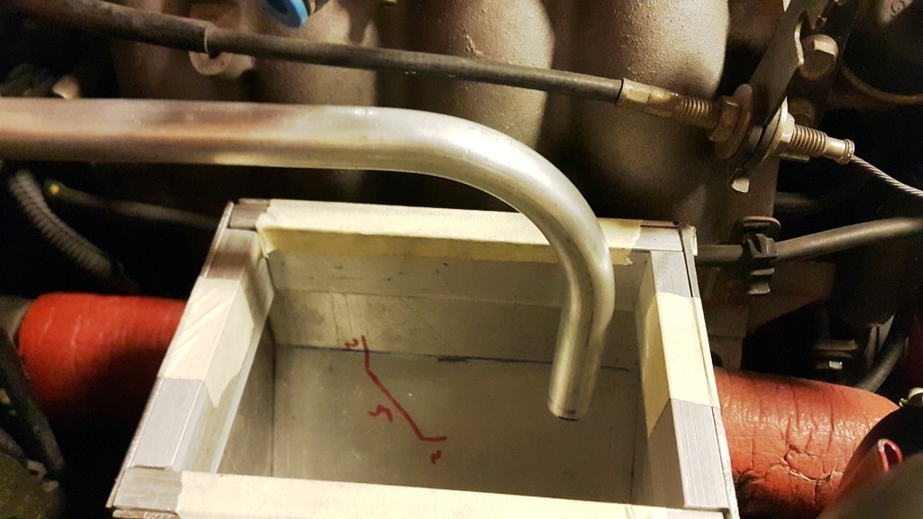
Anyway... I started bending. The tubing, that is.
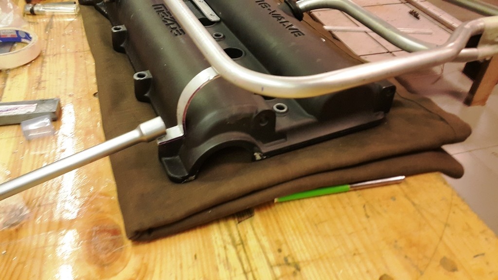
Not bad for a first timer:
I was pretty convinced I would have to try at least 3 or 4 times to get the right shape, but got it on the first try.
(My trick was marking the distance on the tubing and then lining that mark with the 45 degree indicator on the bender. Worked pretty good for me)
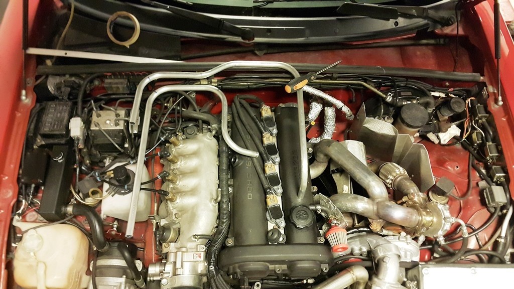
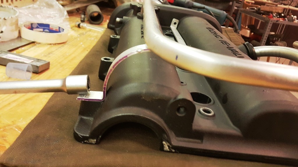
The valve cover would have to come out for the next step...
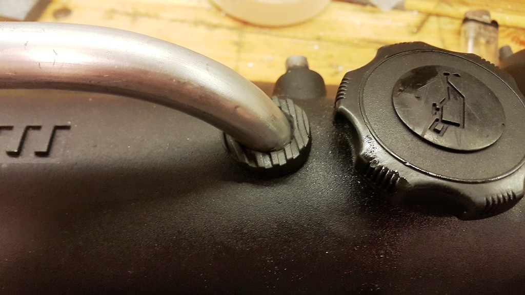
Rather than welding the tubing to the valve cover, I had decided to use grommets.
I mean, PVC valve has a grommet, and the car does not catch fire, right?
Also, using grommets meant removing the valve cover would not be a pain in the ***.
So I drilled the valve cover and promptly forgot to take a picture.
img just picture GC drilling the valve cover while holding his breath /img
The grommet is tight. Like Hustler joke tight:
Last edited by Godless Commie; Jun 18, 2019 at 08:37 PM.
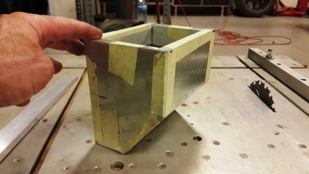
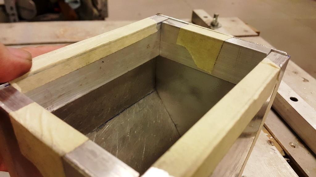
I wanted to make the top removable, so I needed some "meat" to thread bolts in.
The solution was adding a layer of 30x10 mm aluminum bar on the inside, so I can drill and tap them for the said bolts:
The M4 countersunk bolt is for illustration purposes.
I will drill and tap both the tops and the bottoms of the 30x10 mm bars.
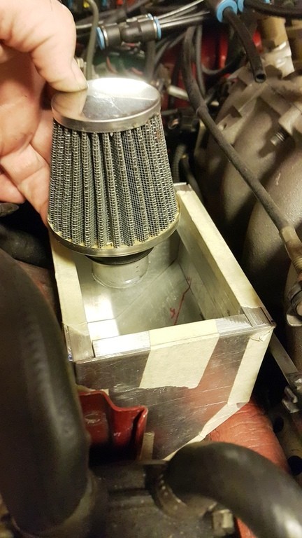
The top side will be for the cover - obviously, and a mesh will be secured to the bottom side of the said bars to contain baffling material (basically some steel wool)
Inlet ports from the engine will extend below the baffling...
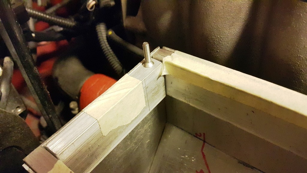
I can almost hear you asking how I am planning on draining this breather tank...
There will be a sight glass on the side (not pictured - yet).
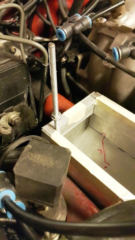
And, I will incorporate a thin (like 6 mm OD) aluminum tube into the breather tank, which will extend all the way to the bottom...
The M6 threaded rod represents that tubing in this pic - please use your imagination, because I have not yet sourced that tubing...
Said tubing will be capped during normal use.
I will thread the inside and use a bolt to plug it.
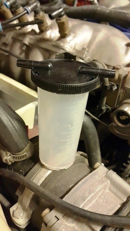
And, the intake manifold has oodles of vacuum when the engine is idling, right?
All I have to do is remove a vacuum line from the IM, attach this fluid collector thingie (one side to the said tubing and the other to the vac port), and idle the engine for a bit...
No mess, no problem.
With the vaccuum and collector idea you're essentially making a second, smaller, catch can/tank, but without baffles so it will possibly just suck oil vapours into the engine (granted only for the short time you're emptying)
Would it be simpler to just add a drainage line (with an inline tap/valve) from the bottom of the can leading to some kind of convenient area you can collect the liquid for disposal? (if you've got room?)
That may be even simpler than the siphon tube idea, instead of unplugging and moving vac lines just hold a cup under the drain tube and open the valve every few weeks (or however often)
9/16 should be fine, especially with smooth bends. Are you opening up the internal passages in the valve cover?
The vacuum extraction drain is more complex than most of us would choose but will work. A simple gravity drain hose being occasionally emptied into a cup would likely suffice.


 0
0