

Honda intake manifold


Elite Member

Joined: Feb 2007
Posts: 1,612
Total Cats: 821
From: Columbus, OH
Thought you guys should know, it didn't work out so bad. I'm going to weld those bungs shut later and smooth it out in there. A very small bit of work with the grinder and the OE fuel rail works. Also, fuel lines re-routing in the future, and the vapor canister needs to go.
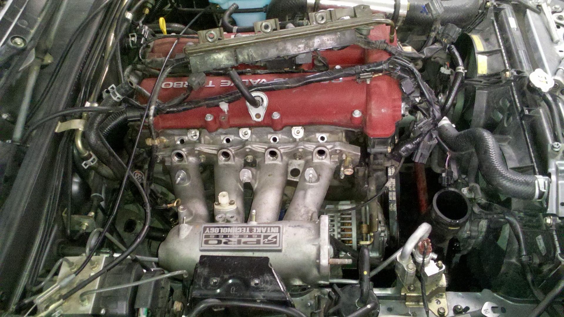
Much like what this guy did. ^^^^^^
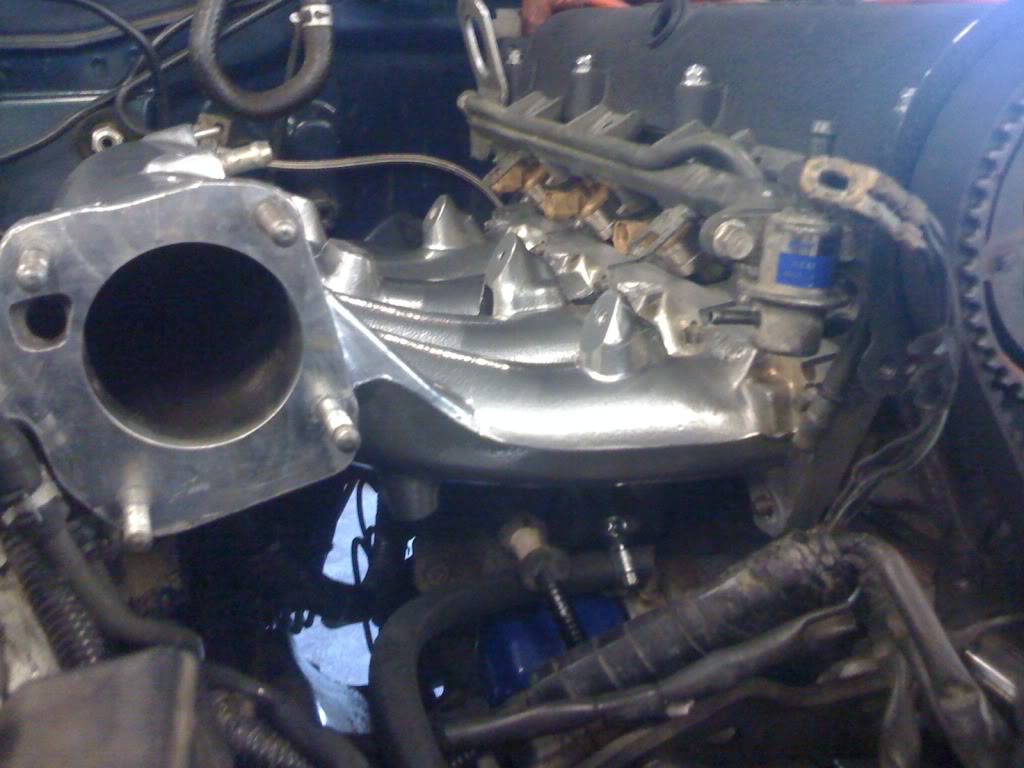
In my photo^ you can see that a lot of material was removed from the flange as compared to chance91's photo. The honda flange has a coolant passage at the front in addition to fuel injector bosses in the mani flange. Obviously we dont need any of this junk on the miata head. A LOT of material was removed from the "stock" honda flange. I didnt just "use a honda flange on a mazda." Every mounting hole used on a honda was plug welded as they simply dont line up. The flange was then clamped to a miataroadster phenolic intake gasket and new holes were drilled from the back.
In the next photo you can see the cut line that goes directly through the preexisting, honda, mounting holes. You can see whats left of the plug welds for the injector bosses as well. You will then notice the relocation of mounting hole for a miata head
Whether you believe it or not, port shape, size and spacing is nearly identical to the mazda head. Only a small amount of porting was required on the outside edges of 1 and 4 runners to match a miata intake gasket.
Reply
 0
0

0

Elite Member
Joined: Feb 2007
Posts: 1,612
Total Cats: 821
From: Columbus, OH
Unfortunatley, no. I didnt have my phone on me when i stopped by to see everything layed out and talk over the plan. Maybe chance91 will see this convo and post a pic from his. He appears to be doing it the same way i did from his photos.
a quick shitty rendering of what it looked like from the head's P.O.V.
(( ) ( ) ( ) ( ))
a quick shitty rendering of what it looked like from the head's P.O.V.
(( ) ( ) ( ) ( ))
Reply
0
0
Unfortunatley, no. I didnt have my phone on me when i stopped by to see everything layed out and talk over the plan. Maybe chance91 will see this convo and post a pic from his. He appears to be doing it the same way i did from his photos.
a quick shitty rendering of what it looked like from the head's P.O.V.
(( ) ( ) ( ) ( ))
a quick shitty rendering of what it looked like from the head's P.O.V.
(( ) ( ) ( ) ( ))
That's why the others here have been hybriding the two.
Reply
0
0

Senior Member
iTrader: (5)
Joined: Jan 2008
Posts: 1,260
Total Cats: 5
From: Central, TX / Bay area, CA
The $150 is just to weld them together, NOT to port match or plug any additional passages. I dont think its that much more work but someone needs to send me one so I can actually see it in person.
Reply
0
0

Doward is right. The ports are about .5 to 1mm at the very most in any place. They center on each other perfectly, the honda ones are just fractionally larger on 1 and 4. It will require very light matching of the HEAD not the manifold, imo. Im not very fast with projects because I work too much. FmII install is ahead of the mani. But I think this way is simpler and more true to the skunkII design this way.
You do need to use aluminum rod as plugs for the injector holes, and then port those bungs smooth on the inside. This is where im at right now.
There are pics on mazdaspeed ill get later of my build showing the spacing. Its crazy
You do need to use aluminum rod as plugs for the injector holes, and then port those bungs smooth on the inside. This is where im at right now.
There are pics on mazdaspeed ill get later of my build showing the spacing. Its crazy
Reply
0
0
Right, the port matching isn't an issue as long as you use the Miata flange. Then the ports will be perfect. Or as perfect as stock... and that's how people are having success.
Reply
0
0
You need to port match the weld job and the runners, when you slap the two together, I would assume. Even if the weld doesn't penetrate all the way which is should, the runners aren't going to be perfectly lined up between junction of honda manifold and miata intake manifold, any more than they are at the head. Which they are close, but are you following me there?
Either way, I'm pretty sure this will be just as well as welding the flange on. Its not so much an issue of flow and such as it is getting it bolted onto the car. That's why people are welding it I'd assume.
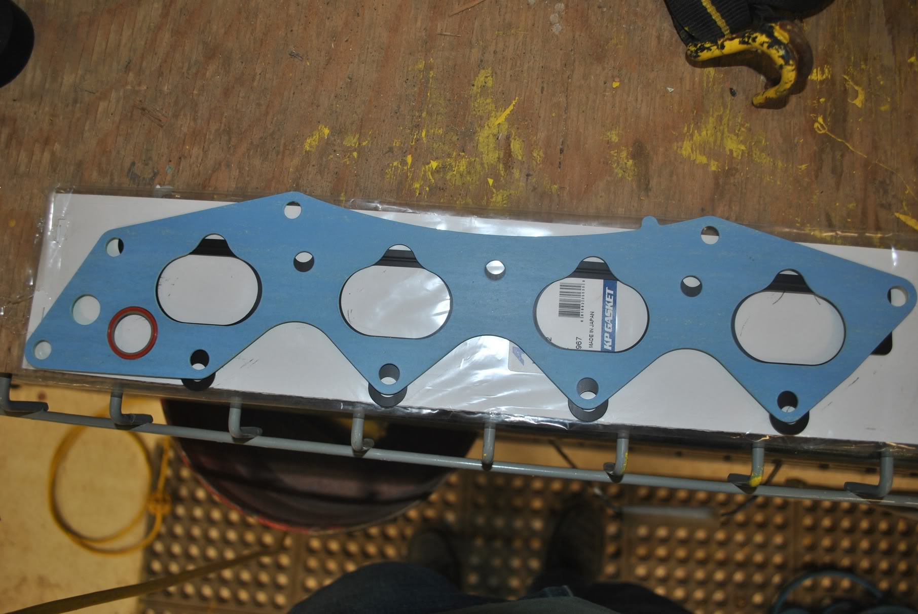
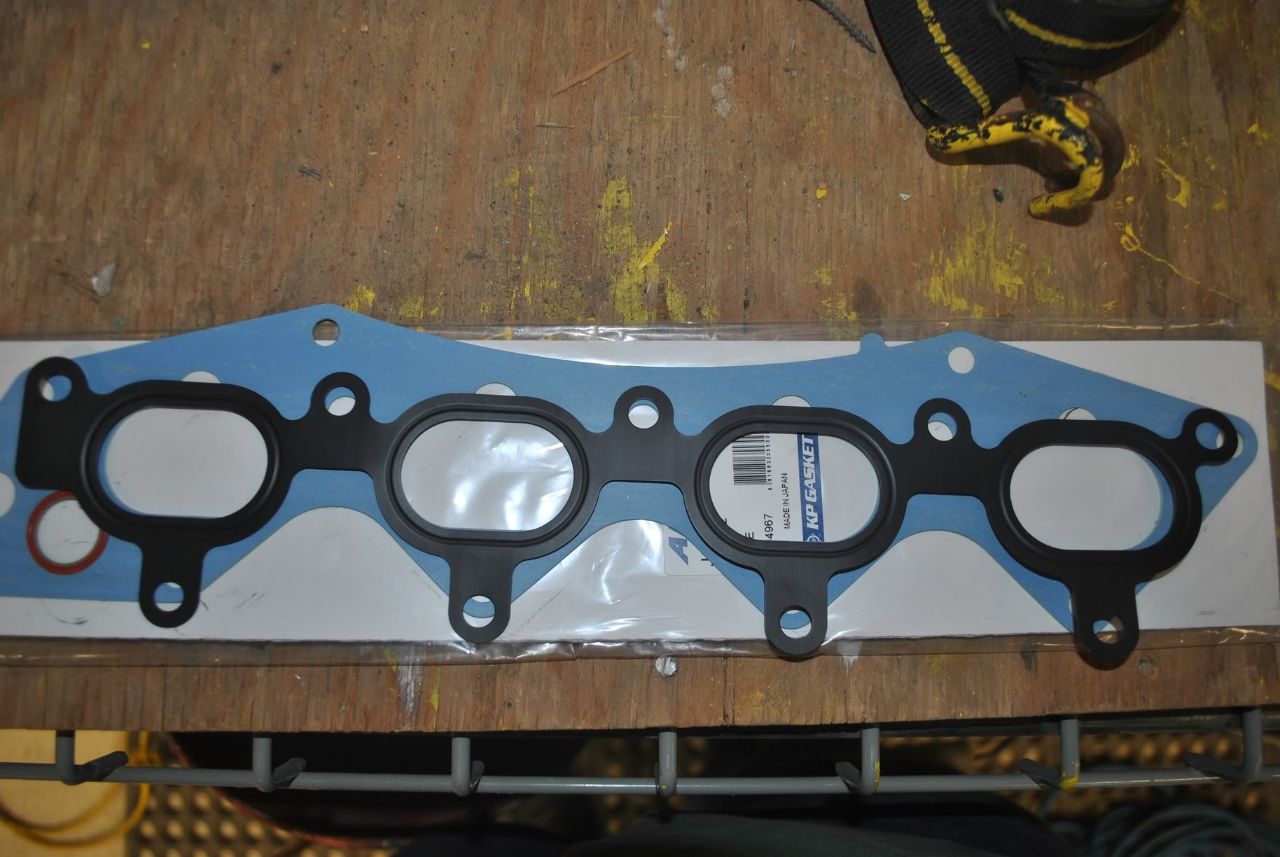
here's a few decent shots of the two gaskets. Also, a GSR manifold might be awesome, its got two sets of runners that can be triggered to switch over, and a solenoid that I think the Hydra can trigger. This is another thing I'll work on. Its like vics only better I think.
Either way, I'm pretty sure this will be just as well as welding the flange on. Its not so much an issue of flow and such as it is getting it bolted onto the car. That's why people are welding it I'd assume.
here's a few decent shots of the two gaskets. Also, a GSR manifold might be awesome, its got two sets of runners that can be triggered to switch over, and a solenoid that I think the Hydra can trigger. This is another thing I'll work on. Its like vics only better I think.
Reply
0
0
Those are part of the injector bungs. I am using aluminum rod stock and plugging most of it, and filling the rest with a TIG. Then flushing the flange up and matching the port with a dremel.
Trust me, I'm not THAT retarded. Its not terribly difficult if you fashion plugs. Use aluminum rod and cut it at angles that fit the manifold well.
Trust me, I'm not THAT retarded. Its not terribly difficult if you fashion plugs. Use aluminum rod and cut it at angles that fit the manifold well.
Reply
0
0
Elite Member
Joined: Feb 2007
Posts: 1,612
Total Cats: 821
From: Columbus, OH
Those are part of the injector bungs. I am using aluminum rod stock and plugging most of it, and filling the rest with a TIG. Then flushing the flange up and matching the port with a dremel.
Trust me, I'm not THAT retarded. Its not terribly difficult if you fashion plugs. Use aluminum rod and cut it at angles that fit the manifold well.
Trust me, I'm not THAT retarded. Its not terribly difficult if you fashion plugs. Use aluminum rod and cut it at angles that fit the manifold well.
Reply
0
0
Senior Member
iTrader: (5)
Joined: Jan 2008
Posts: 1,260
Total Cats: 5
From: Central, TX / Bay area, CA
Those are part of the injector bungs. I am using aluminum rod stock and plugging most of it, and filling the rest with a TIG. Then flushing the flange up and matching the port with a dremel.
Trust me, I'm not THAT retarded. Its not terribly difficult if you fashion plugs. Use aluminum rod and cut it at angles that fit the manifold well.
Trust me, I'm not THAT retarded. Its not terribly difficult if you fashion plugs. Use aluminum rod and cut it at angles that fit the manifold well.
Ill have to see one first, but I would plan on cutting the whole part off that has the injector bungs in it and welding the strait part of the runners to the remains of a stocker or a new flange.
Reply
0
0
Just picked this up. 
Thinking about smoothing out the joints most of the way with my Dremel and then sending it out to be extrude-honed, and possibly sending it out again for a TB/inlet bore from maxbore.com. This would be after a trial fitment, of course, to make sure everything's good to go.
Lev - You just re-routed the throttle cable? Anything more to it than that? The Honda TPS, easy to get MS to control it?
Reply
0
0
Oh yeah, he's at summer camp. Forgot about that.
Thanks for stepping up and providing the answers. I'll look more into the TPS as I get closer to coming home. Electrics are still not my strong suit.
Thanks for stepping up and providing the answers. I'll look more into the TPS as I get closer to coming home. Electrics are still not my strong suit.
Reply
0
0

Reviving this thread, I'll be using a Victor X on my 2.0 liter hopefully in the next month or 2. Shooting for 400+ whp, possibly close to 500. I'll get pics and some info up when it comes. Hope to have a mani like post 120.
Reply
0
0

bringin this bish back from the dead so i dont have to start a new thread:
are the lower intake manifolds (part that bolts to head) for the nb1 and nb2 the same? i know one has VICS and the other, VTCS. but i really dont care... since i will need it just for the flange...
and if your still wondering why im tryna use a nb2 mani on my nb1 head, its cause i see a lot more nb2 partouts than i do nb1 partouts....
Reply
0
0


