

Modding the Air Intake for MAF delete / IAT install


Thread Starter
Junior Member
Joined: Feb 2015
Posts: 144
Total Cats: 6
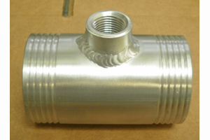
Getting ready to install my DIYPNP and I'm curious what the preferred method is these days for modifying the stock intake to accommodate an IAT sensor. I came across this post and that seemed like a good way to handle it.
Does anyone make a straight pipe with an IAT bung to bypass the MAF and go to the stock airbox? Assuming that would work. Or is the cone style a better option?
Does anyone make a straight pipe with an IAT bung to bypass the MAF and go to the stock airbox? Assuming that would work. Or is the cone style a better option?
Reply
 0
0

0


silicone intakes?
http://www.siliconeintakes.com/holse...er/-p-500.html
though you'd need 3/8NPT for a GM IAT
http://www.siliconeintakes.com/holse...er/-p-500.html
though you'd need 3/8NPT for a GM IAT
Reply
0
0

Reply
0
0
Reply
0
0
Thread Starter
Junior Member
Joined: Feb 2015
Posts: 144
Total Cats: 6
I really like this solution
I'm leaning toward this route. The only thing stopping me is being realistic about how long "short-term" will actually be.
Reply
0
0
if nb then 2.75
don't remember na size
the other up-side to my solution is that the whole sensor is inside the airbox, and in the path of airflow, thus significantly helping reduce or prevent ait heat soak
don't remember na size
the other up-side to my solution is that the whole sensor is inside the airbox, and in the path of airflow, thus significantly helping reduce or prevent ait heat soak
Reply
0
0

Due to radiator heat soak? I can move it to the outside top of the elbow. Or draw up an inline adapter to be 3D printed similar to the metal one so you can put it wherever your heart desires.
Last edited by cyotani; May 21, 2015 at 11:44 AM.
Reply
0
0

Joined: Sep 2005
Posts: 34,381
Total Cats: 7,504
From: Chicago. (The less-murder part.)
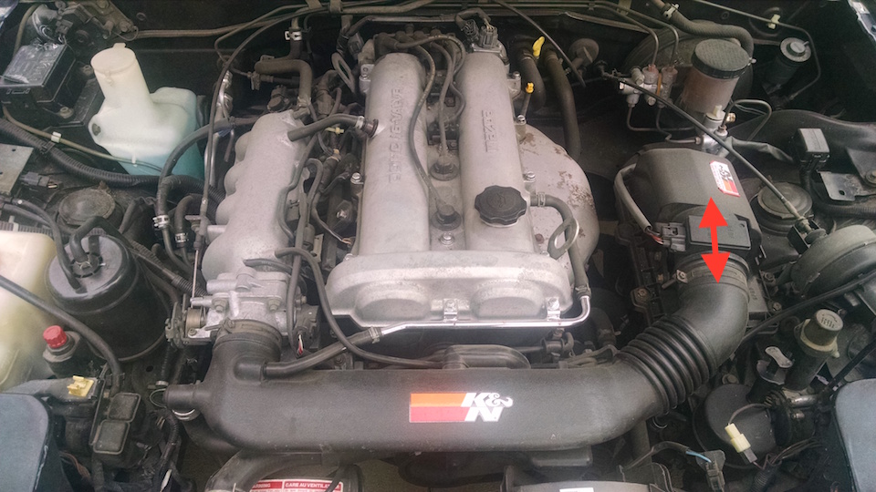
It's rare that I agree with Scott, but this is, in fact, not an especially good spot despite the fact that both Bell and FM put theirs there.
Placing an IAT sensor directly behind the radiator exposes it to a hell of a lot of hot air, and even though the fancy GM-style "open element" IAT sensors aren't supposed to heat-soak externally, they always seem to. The result is artificially elevated IAT readings.
I had reasonably good success drilling and tapping the cold-side end tank of my intercooler, and placing the sensor there. It would obviously heak-soak just a tad after you parked the car hot, but once you re-started it and got moving, the sensor seemed to cool off and give believable readings while in off-boost cruise.
Reply
0
0
Joined: Sep 2005
Posts: 34,381
Total Cats: 7,504
From: Chicago. (The less-murder part.)
Reply
0
0
I'll revist my IAT location and try to figure out a better solution.
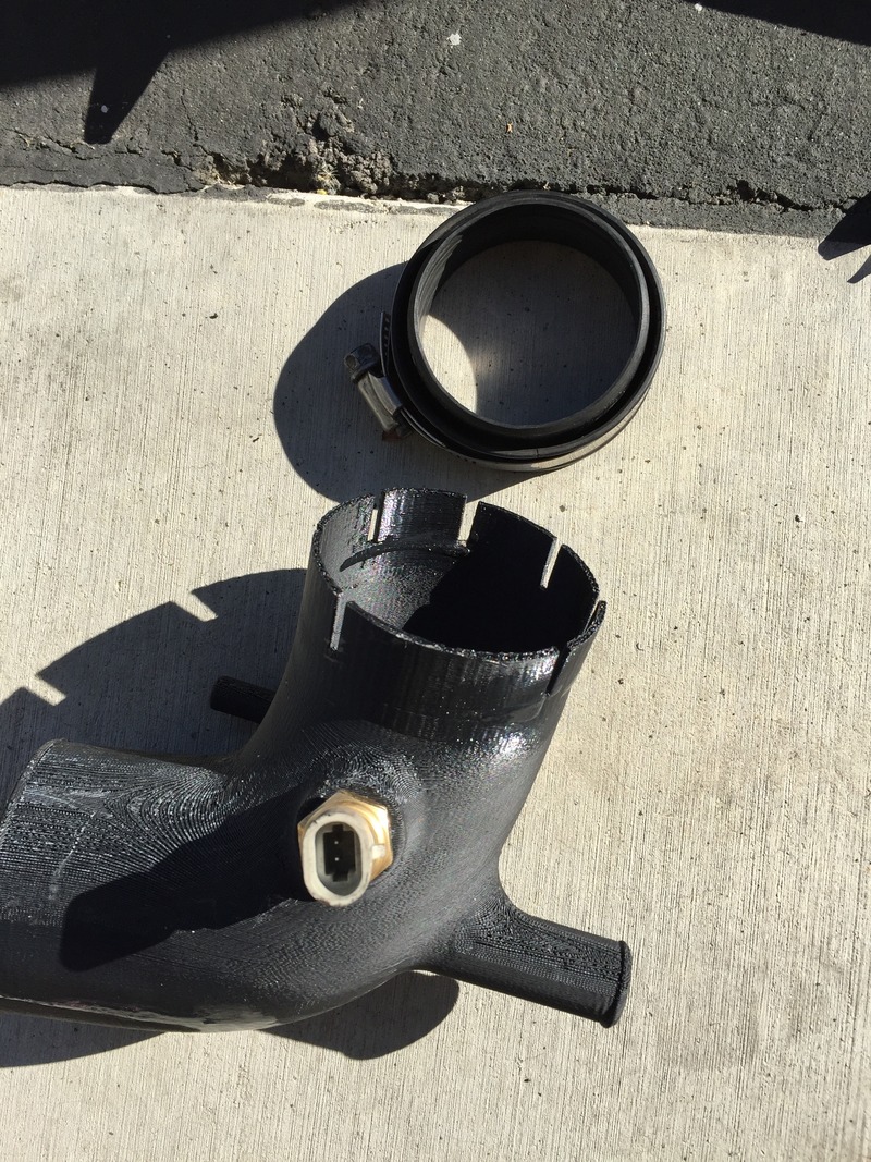
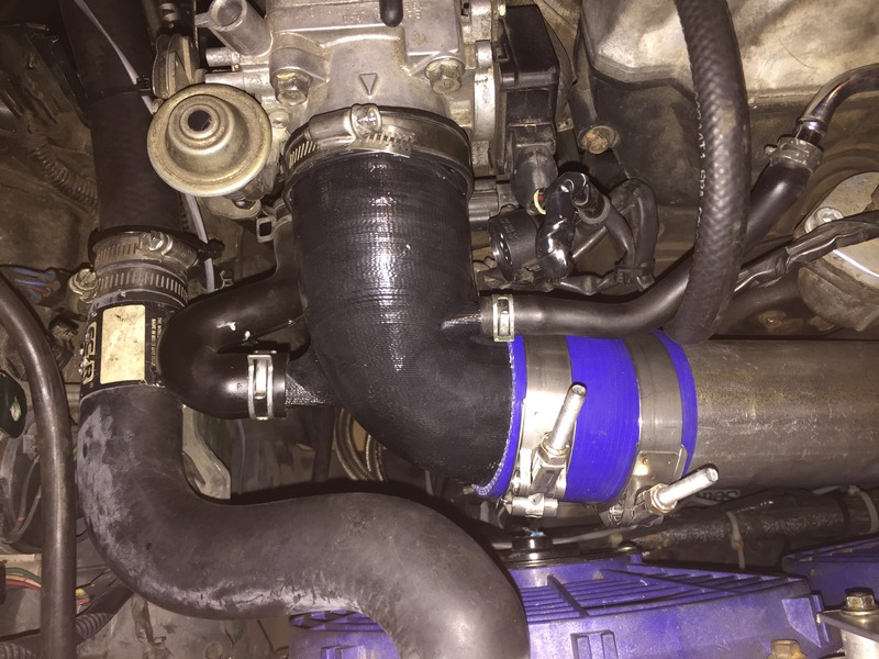
Material is 3d printed ABS then acetone vapor bath which helps smooth the part, seal it, and bond the layers together better. I printed this at 0.12" wall. Replicating the 1.6L OEM tabs and rubber mounting style did not work well. The tabs were too thin. I switched it to the traditional hose bead and silicone coupler mounting style. I want to start experimenting with nylon which is less brittle than ABS and might be a better material choice for parts like this.
I design aftermarket intake for a living and we run 3D printed prototypes for 2-3 months on vehicle while the production tooling is being made. I have not seen any failure or degradation in the 3D printed ABS parts. We usually use 0.15" wall thickness. However, these are street vehicles that don't see the extreme abuse of track cars. I've run that intake at 1 track event so far without any issues. I'll be keeping a close eye on it and always take the spare stock tube with me.
I design aftermarket intake for a living and we run 3D printed prototypes for 2-3 months on vehicle while the production tooling is being made. I have not seen any failure or degradation in the 3D printed ABS parts. We usually use 0.15" wall thickness. However, these are street vehicles that don't see the extreme abuse of track cars. I've run that intake at 1 track event so far without any issues. I'll be keeping a close eye on it and always take the spare stock tube with me.
Reply
0
0
ShmoozerJoe has one of those things (one of those cobra looking intake tubes), and (correc me if I'm wrong, Joe) it's ABS plastic.
And his cracked last wednesday. Right down the middle
And his cracked last wednesday. Right down the middle
Reply
0
0


