

Thread for naturally aspirated manifold design


Thread Starter

Joined: Jul 2012
Posts: 792
Total Cats: 143
From: durham NC
Runner lengths at different RPM (stock 01 intake cam):
5000 17.17533333
5500 15.17412121
6000 13.50644444
6500 12.09533333
4th wave looks like this:
5000 11.672
5500 10.17109091
6000 8.920333333
6500 7.862
It seems to me that if you are going to drop down to the 4th wave you might as well straighten the runners and ditch the squaretop entirely. As far as the bounds of what seems possible to fit in the car without cutting. ~15" runners with a curve and maybe 13" runners that are straight. Meaning, you could definitely do just about any length with the 4th wave using straight runners, and 5500 RPM with curved runners.
Last edited by asmasm; Dec 30, 2015 at 01:01 PM.
Reply
 0
0

0
I would pick the RPM that's right in the middle of your RPMs when at WOT going through the gears. With a 7,000 redline, and dropping to 5,000-5,500 at each gear change, I'd pick something around 6,000-6,200. I think you're pretty close.
Reply
0
0
Thread Starter
Joined: Jul 2012
Posts: 792
Total Cats: 143
From: durham NC
Also, looking at where some runner lengths overlap:
a 15.2" runner gives a third wave of 5500 and a fourth wave of 4100
a 13" runner gives a third wave at 6150 and a fourth wave at 4600
an 11.6" runner gives a third wave at 6700 and a fourth wave at 5000 <- this would be roughly the squaretop's dimensions. Meaning it is using the 4th wave for peak torque at 5000ish and the third wave at 6700 is holding up the top end.
Also, 16" runner would be second wave at 7900, third wave at 5200, and fourth wave at 3950.
After I put my VVT engine into my car I will pull the intake manifold and do a very large expanding foam pour and then 3d scan it to see what could be squeezed into the underhood area.
Last edited by asmasm; Dec 30, 2015 at 07:23 PM.
Reply
0
0

Junior Member
Joined: Jan 2015
Posts: 272
Total Cats: -25
Peeked under my hood, not a bunch of spack left to increase the plenum volume of the squaretop. If i had to make a guess I would say shy of 1L.
It would be nice if S2 would get their behind in gear, they have a prototype on Project-G's car ive seen in photos. Its taken them multiple revisions already to make an improvemet.
It would be nice if S2 would get their behind in gear, they have a prototype on Project-G's car ive seen in photos. Its taken them multiple revisions already to make an improvemet.
Reply
0
0
Junior Member
Joined: Jan 2015
Posts: 272
Total Cats: -25
it would be super easy to reduce the runner length by 1/2" by cuttling the web out of the plenum and tapering the opening the intake runners. This would also add a small amount to the plenum volume.
Reply
0
0

Thread Starter
Joined: Jul 2012
Posts: 792
Total Cats: 143
From: durham NC
I don't think we should get hung up on runner length in .5" increments because of what that math predicts. It's going to take A/B Dyno testing to see what adjustments that small do. I measured the squaretop runner with a bent up piece of 14 gauge wire so there is a lack of accuracy from the start.
Reply
0
0
Junior Member
Joined: Jan 2015
Posts: 272
Total Cats: -25
if you can predict that the math is correct it will give a greater level of confidence.
I will have significant access to a dyno come spring but im not ready to cut up my square top just yet. An A B test with these changes should be able to easily be done on a cheaper 01-05 manifold. VVT may compound the difficulty.
I will have significant access to a dyno come spring but im not ready to cut up my square top just yet. An A B test with these changes should be able to easily be done on a cheaper 01-05 manifold. VVT may compound the difficulty.
Reply
0
0
Thread Starter
Joined: Jul 2012
Posts: 792
Total Cats: 143
From: durham NC
Aside from the huge increase in complexity and cost, how would you deal with the throttle body moving and causing all of the intake tubing and filter to move? Seems doable for an ITB setup but would add a new dimension to tuning complexity. All the examples I have seen show the intake getting longer and shorter repeatedly through the rev range so it isn't as simple as long at idle, short at redline.
A manually adjustable length runner might be more doable. You would have to give up having control of runner taper and you would likely introduce a big step where the telescopic tubes meet. I think it would be better to design an intake manifold that is modular such that it can use the same molds for the plenum and multiple runner designs can be used as an option. Fine tuning runner lengths from there can be done with spacers at the port.
A manually adjustable length runner might be more doable. You would have to give up having control of runner taper and you would likely introduce a big step where the telescopic tubes meet. I think it would be better to design an intake manifold that is modular such that it can use the same molds for the plenum and multiple runner designs can be used as an option. Fine tuning runner lengths from there can be done with spacers at the port.
Reply
1
1
It's simple, really. The throttle body and intake runners (with semi-circle cross sections) are attached to a fixed "intake manifold". From the exterior, no change in runner length is visible. The only changes occur on the inside of the intake manifold. The runners are wrapped around the center plenum, and the plenum "liner" simply rotates within the plenum+runners to lengthen/shorten the runners.
I do wish I had the know-how and money to actually manufacture sh*t. It seems to me like it would be way easier to implement in practice when compared with the R&D required to produce ideally sized resonance chambers and all that BS to try tuning the system to a specific RPM. You build it, then you put it on a dyno, do a dozen pulls or so at different servo-controlled runner lengths, then tune your maps to the highest torque numbers at each RPM point.
I do wish I had the know-how and money to actually manufacture sh*t. It seems to me like it would be way easier to implement in practice when compared with the R&D required to produce ideally sized resonance chambers and all that BS to try tuning the system to a specific RPM. You build it, then you put it on a dyno, do a dozen pulls or so at different servo-controlled runner lengths, then tune your maps to the highest torque numbers at each RPM point.
Reply
0
0
Thread Starter
Joined: Jul 2012
Posts: 792
Total Cats: 143
From: durham NC
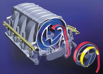
I still don't follow. This is the best variable IM design I have seen and it is super complicated compared to building a static manifold:
It also has the side effect of being a variable plenum volume, which I am sure is outweighed by the gains made being able to adjust the runner lengths.
It also has the side effect of being a variable plenum volume, which I am sure is outweighed by the gains made being able to adjust the runner lengths.
Last edited by asmasm; Dec 31, 2015 at 12:47 PM.
Reply
0
0

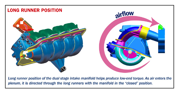
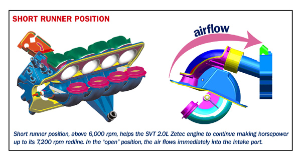
I am guessing he is talking something along the lines of what was on the Ford Zetec.
It has a moveable barrel with part of the long runners in it. When it rotates (via servo) the runner length changes.

It has a moveable barrel with part of the long runners in it. When it rotates (via servo) the runner length changes.
Reply
0
0
For the concept consider this: Imagine a nestle quick can

Except turn it on it's side, this is the base exterior manifold. Now add 4 Toruses to the outside of the nestle quick can

Only the outside "half" of the red circle is considered. When the toruses are added, it would appear like a super thick ***** with 4 ribs on it.
Next take your inake manifold runner cut off

and add it so that the centerline of the short runners meets the half toruses at a tangent to their own centerline. The short runners should feed directly into the toruses at one direction, while cutting off the other side of the toruses. (If you threw a marble into the short runner really fast, it would smoothly transition to the torus, and just before it made a full revolution inside of the torus it would hit the top side of the short runner) Now it will look like you have 4 snails with a Nestle Quick can going through them. Finally, add an attachment point for your throttle body in lieu of the lid of the nestle quick can. This is the outside of the manifold.
The last piece of the puzzle is the manifold "liner", which looks much like the original nestle quick can except smaller such that it fits inside of the first nestle quick can and rotates freely. leave the top off of this nestle quick can (next to the throttle body) and then cut 4 holes into the wall of the quick can so that air can flow into the runners. Each hole should match up with a half-torus. Lastly, create a smooth transition from the interior can to the torus in the direction of the short runners. This transition will serve both to "gently" turn the air in the direction of the short runners, and to prevent large quantities of air from resonating inside of the unused portion of the torus. An airflow facilitating tube can be added on the outside can connecting the back end of the unused portion of the toruses to a vent hole just behind the throttle body to reduce pressure differential in the unused portion of the toruses. Set the whole thing up on bearings and a rotational servo, and go.
BMW has a similar concept, though I think it's a bit too complicated. Their engineers have probably spent more time working on the concept though:
Reply
1
1
Thread Starter
Joined: Jul 2012
Posts: 792
Total Cats: 143
From: durham NC
Can we bring this thread back to reality? That ford manifold operates as a switch between short and long runners- it doesn't provide continuously variable runner length control.
I actually want to build something. A continuously variable length intake manifold would be awesome but I think things like materials for sealing and wear, and packaging it, would make it really difficult.
I actually want to build something. A continuously variable length intake manifold would be awesome but I think things like materials for sealing and wear, and packaging it, would make it really difficult.
Reply
2
2
Where do you think a runner length of 8.5" would put the peak torque? 6300ish?
I ask because my Skunk2 manifold is about 8.5" and has a 1.82L plenum and I am trying to estimate the low and mid range loss.
I ask because my Skunk2 manifold is about 8.5" and has a 1.82L plenum and I am trying to estimate the low and mid range loss.
Reply
0
0
Thread Starter
Joined: Jul 2012
Posts: 792
Total Cats: 143
From: durham NC
My spreadsheet says 6400 on the fourth wave. You have to look at it where each wave sits. That length its only getting the 4th wave in the rev range (third wave at 8600).
Last edited by asmasm; Dec 31, 2015 at 03:56 PM.
Reply
0
0
Thread Starter
Joined: Jul 2012
Posts: 792
Total Cats: 143
From: durham NC
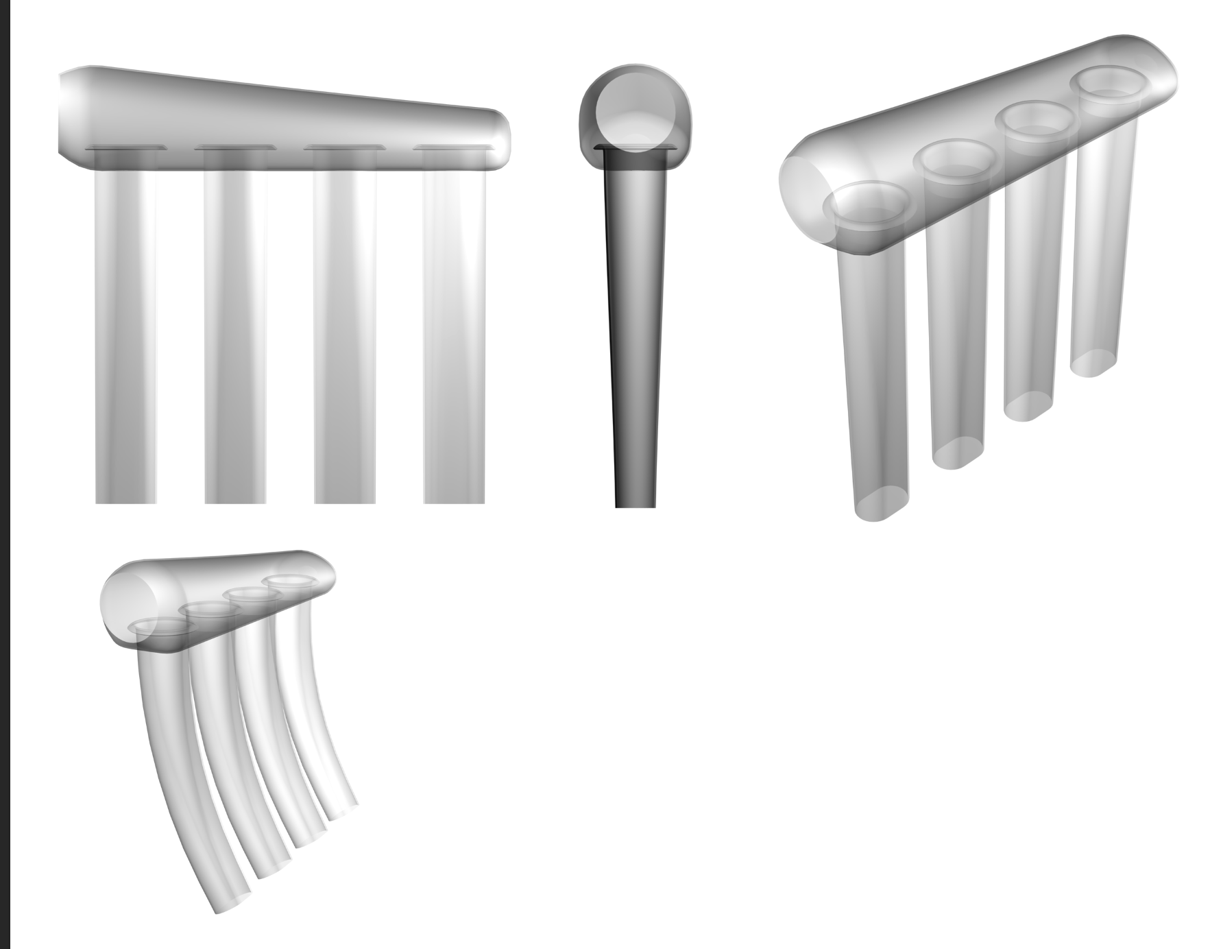
This is a quick block-out for 11.5" runners and a 1.8L plenum. The intake ports on the head are angled down 5-10 degrees so the runners will need a gentle bend to get everything to fit. I am also planning to make a silicone casting of the port geometry since it looks like the flange is actually placed at an angle off axis compared to the port.
Reply
0
0
Junior Member
Joined: Jan 2015
Posts: 272
Total Cats: -25
This is a quick block-out for 11.5" runners and a 1.8L plenum. The intake ports on the head are angled down 5-10 degrees so the runners will need a gentle bend to get everything to fit. I am also planning to make a silicone casting of the port geometry since it looks like the flange is actually placed at an angle off axis compared to the port.
Reply
0
0


