Ducting and airflow
 07-20-2009, 12:58 AM
#1
Former Vendor

Thread Starter
iTrader: (31)

Join Date: Nov 2006
Location: Sunnyvale, CA
Posts: 15,442
Total Cats: 2,100
I'm re-shuffling my ****, yet again. Last event at WSIR, I stacked the intercooler and oil cooler on top of each other, sealed them together, and stuck them in front of the radiator. Oil temps were LOW, like 180 degrees, but coolant temps were 240 and rising on the 2nd hotlap.
So, back to the drawing board. With constant overheating issues, and more power on the way, I don't think there's any way around it except to feed fresh air to the radiator at all costs.
Therefore:
-IC gets laid back, ducted to the front mouth, exits underneath the radiator
-Radiator stays in stock location, but gets fully sealed to the mouth
-Oil cooler gets hidden where the OEM crash structure normally is. It's so big I don't even know if I'll need any ducting to it.
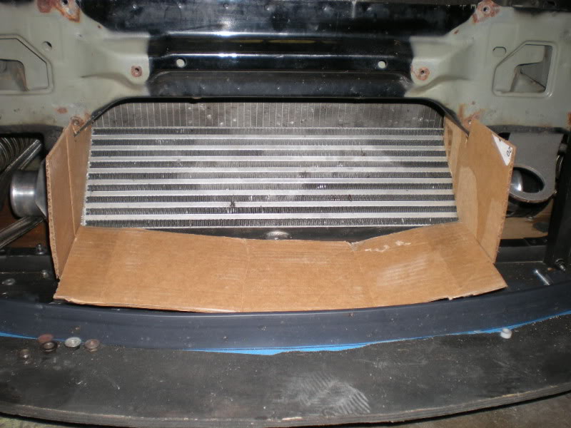
Beginning of the IC duct:
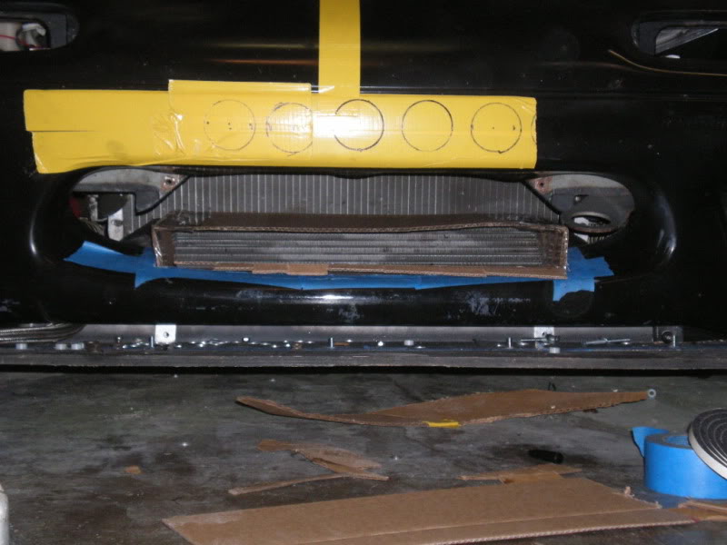
Final IC duct:
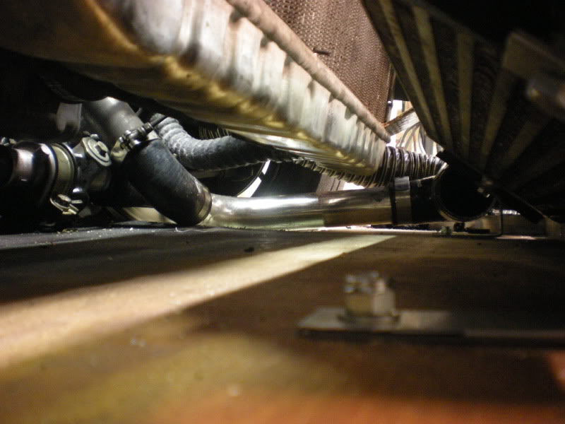
Oil cooler location:
Comments? Hustler thinks the IC won't get enough air. The surface area of the opening to that duct is about 30% of the surface area of the core. I also have water injection, 3gph above 6psi, so I am hoping to not have IAT issues either way. Oil temps are essentially a non-issue with this massive new cooler, so I can tuck that away wherever I want. If I see it getting warm, I can punch a few holes in the bumper or figure out a ducting scheme to remedy that.
So, back to the drawing board. With constant overheating issues, and more power on the way, I don't think there's any way around it except to feed fresh air to the radiator at all costs.
Therefore:
-IC gets laid back, ducted to the front mouth, exits underneath the radiator
-Radiator stays in stock location, but gets fully sealed to the mouth
-Oil cooler gets hidden where the OEM crash structure normally is. It's so big I don't even know if I'll need any ducting to it.
Beginning of the IC duct:
Final IC duct:
Oil cooler location:
Comments? Hustler thinks the IC won't get enough air. The surface area of the opening to that duct is about 30% of the surface area of the core. I also have water injection, 3gph above 6psi, so I am hoping to not have IAT issues either way. Oil temps are essentially a non-issue with this massive new cooler, so I can tuck that away wherever I want. If I see it getting warm, I can punch a few holes in the bumper or figure out a ducting scheme to remedy that.

Reply
 0
0

0
 07-20-2009, 01:15 AM
#6
You dont need to cut anything. What are you talking about. The bumper can easily remain stock and still implement a full vmount setup. If you can't envision that then there is no helping you.
Just because Dave cut the hole in his bumper has nothing to do with the actual setup. Its just something he chose to add.
Just because Dave cut the hole in his bumper has nothing to do with the actual setup. Its just something he chose to add.
Reply
0
0
07-20-2009, 01:30 AM
#7
Former Vendor
Thread Starter
iTrader: (31)
Join Date: Nov 2006
Location: Sunnyvale, CA
Posts: 15,442
Total Cats: 2,100
In the stock location, there's around 3" between the splitter and the bottom of the radiator. I've basically laid the intercooler back so it vents under there. I guess I've moved the intercooler into the location it would sit in a v-mount setup, but not the radiator since it still sees full airflow in the location it's in. Do you think tilting the rad forward would give enough of a benefit to warrant the work? I'm really not keen on cutting the radiator support out, either.
Reply
0
0
07-20-2009, 01:38 AM
#8
In the stock location, there's around 3" between the splitter and the bottom of the radiator. I've basically laid the intercooler back so it vents under there. I guess I've moved the intercooler into the location it would sit in a v-mount setup, but not the radiator since it still sees full airflow in the location it's in. Do you think tilting the rad forward would give enough of a benefit to warrant the work? I'm really not keen on cutting the radiator support out, either.
Reply
0
0
07-20-2009, 01:45 AM
#9
Former Vendor
Thread Starter
iTrader: (31)
Join Date: Nov 2006
Location: Sunnyvale, CA
Posts: 15,442
Total Cats: 2,100
Yeah, there's a big hole cut in the hood. The splitter extends back, the width of the subframe, to the front of the steering rack. I was originally going to put my oil cooler under the steering rack, but I am wary of cutting a hole of any sort under there, on the off chance I go off track. If I were to put some ducting on it, it would have to hang lower than the splitter, and I'll inevitably tear it off on a curb somewhere. The two bolts that attach it to the subframe back there have scrapemarks on them, so I know they touch something.
I'm also wary of trying to pull air underneath the car, since it reduces the low-pressure zone under the car and would have an effect (a big one?) on any diffuser I try to work with in the future.
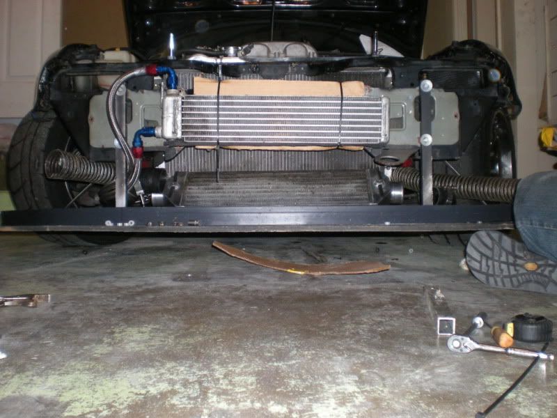
Here's a photo that shows IC angle, space under the radiator, and the splitter length.
I'm also wary of trying to pull air underneath the car, since it reduces the low-pressure zone under the car and would have an effect (a big one?) on any diffuser I try to work with in the future.
Here's a photo that shows IC angle, space under the radiator, and the splitter length.
Reply
0
0
07-20-2009, 01:50 AM
#10
I would have the IC butted up against the rad and sealed with weather stripping. You want to maintain a high pressure region in front of both, and that gaping hole is going to prevent that.
As far as the extractor I mentioned. What I envision is simply like a 2" wide rectangle the length of the ic core starting right where the top of the core is if you drew a straight like down onto the splitter. Then bend down the leading edge about 1/4-1/2". The lip would create the same effect as the hood extractor but be much smaller. Hell, you might not even need to make a lip since the splitter already creates a low pressure region underneath it.
As far as the extractor I mentioned. What I envision is simply like a 2" wide rectangle the length of the ic core starting right where the top of the core is if you drew a straight like down onto the splitter. Then bend down the leading edge about 1/4-1/2". The lip would create the same effect as the hood extractor but be much smaller. Hell, you might not even need to make a lip since the splitter already creates a low pressure region underneath it.
Reply
0
0
07-20-2009, 02:00 AM
#11
Former Vendor
Thread Starter
iTrader: (31)
Join Date: Nov 2006
Location: Sunnyvale, CA
Posts: 15,442
Total Cats: 2,100
In the background on the driver's side, you can see a little piece of cardboard that is the beginning of the duct that will gap the IC and radiator. I figured that I was better off moving the intercooler forward and trying to get some air to trace over the top of the IC ducting into the bottom of the rad, vs. butting it up against the rad and losing an inch or so off the bottom.
"bending the leading edge down about 1/4" is easier said than done, since the splitter is 12mm birchwood. I suppose I could do a rectangular hole and then chicken-wire it.
"bending the leading edge down about 1/4" is easier said than done, since the splitter is 12mm birchwood. I suppose I could do a rectangular hole and then chicken-wire it.
Reply
0
0
07-20-2009, 02:01 AM
#12
Cpt. Slow
iTrader: (25)
Join Date: Oct 2005
Location: Oregon City, OR
Posts: 14,224
Total Cats: 1,146
My issue is with surface area. Your pictures demonstrate the problem perfectly. If you look at your 3rd picture, you can see the top of the radiator, and the bottom is just hidden behind the intercooler, it's a fairly large radiator.
Yet if you look at your second picture, between the top of the cardboard ducting and the bottom of the yellow tape, that's all that's exposed to air, and it's not much. I wouldn't hesitate one bit adding a little drag if it meant it would solve my cooling issues.
Also, NACA ducts would be great on the bottom of your splitter to maybe point some more air up to the radiator, that's a steep angle though.
Reply
0
0
07-20-2009, 02:44 AM
#15
Former Vendor
iTrader: (9)

Join Date: Jan 2008
Location: Bay Area, California
Posts: 929
Total Cats: 9
I remember seeing somewhere that you only need about 1/3 of the surface area of the radiator worth of airflow (because the fins and crap end up taking up 2/3 of that surface area). That's what we are going off of for whether there is a big enough opening.
Reply
0
0
07-20-2009, 02:54 AM
#16
Former Vendor
Thread Starter
iTrader: (31)
Join Date: Nov 2006
Location: Sunnyvale, CA
Posts: 15,442
Total Cats: 2,100
https://www.miataturbo.net/forum/t14760-3/
start at like post 160 and read through to the end. There is some **** that Pats posted that I ignored because I had an IC, but now that I have free air I think I can implement some of it.
I'm also going to put this fans vs. no fans horseshit to bed once and for all. I'm going to leave my current setup (sealed 11" spals) in place, throw a magnehelic gauge into the chamber between the fans and the radiator, and take a pressure measurement. Then remove one fan, test again. If the pressure goes down with the fan removed, then it's a success.
Reply
0
0
07-20-2009, 02:59 AM
#17
Cpt. Slow
iTrader: (25)
Join Date: Oct 2005
Location: Oregon City, OR
Posts: 14,224
Total Cats: 1,146
I'm also going to put this fans vs. no fans horseshit to bed once and for all.
whoops.
start at like post 160 and read through to the end. There is some **** that Pats posted that I ignored because I had an IC, but now that I have free air I think I can implement some of it.
Reply
0
0
07-20-2009, 03:08 AM
#18
I'm Miserable!
iTrader: (16)

Join Date: Dec 2008
Location: where most people are Utarded
Posts: 1,296
Total Cats: 0
This is great info for the rest of us, thanks for testing new ideas! Sav, how long does it take you to get your bumper off, must be pretty quick at it?
Reply
0
0
07-20-2009, 03:33 AM
#20

Just read through that thread. Pat is 100% correct IMHO. Bigger surface area does not increase pressure. Small in, larger out does. The link provided in that thread confirms this. Can't wait til you test this out once and for all with actual proof/data.
off topic/
Pat is a smart ******, I wish he was still here
/off topic
off topic/
Pat is a smart ******, I wish he was still here
/off topic
Reply
0
0


