General Miata Chat A place to talk about anything Miata

Ideal Vacuum Pathway from ITBs to Block

Thread Tools
 
Search this Thread
 
Old 12-18-2019, 10:32 PM
  #1  
Junior Member
Thread Starter
 
Melvin's Avatar
 
Join Date: Oct 2018
Location: Glendora, CA
Posts: 201
Total Cats: -5
Default Ideal Vacuum Pathway from ITBs to Block

Looking to see what is better to run:

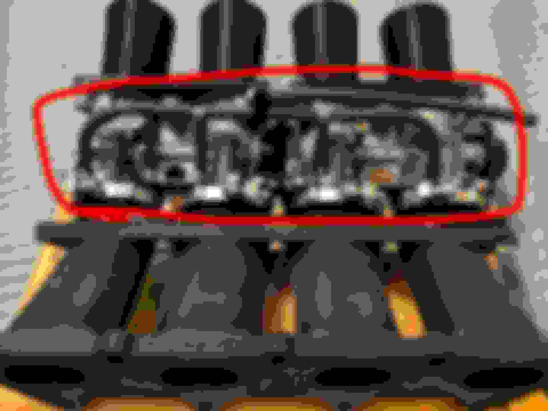
Start from the 4 nipples from the ITBs, then merge into 1 tube, and go into the vacuum block.


Or
Start from 4 nipples and do not merge, plug all 4 into the vacuum block.


It seems like maybe the second one is better for MAP response and achieving equilibrium faster. But the first one would already have the average vacuum as it goes into the block.
I'd appreciate any explanations as to what and why.

Thanks
Melvin is offline  
Old 12-19-2019, 06:50 AM
  #2  
Moderator
iTrader: (12)
 
sixshooter's Avatar
 
Join Date: Nov 2008
Location: Tampa, Florida
Posts: 20,660
Total Cats: 3,011
Default

Average is better than fluttering and pulsing. Response won't be a problem with the volumes that are being moved.
sixshooter is offline  
Old 12-19-2019, 09:10 AM
  #3  
Elite Member
iTrader: (15)
 
Midtenn's Avatar
 
Join Date: Jan 2007
Location: Murfreesboro,TN
Posts: 2,045
Total Cats: 265
Default

The second one is better. You need a large chamber to dampen the pulses and feed a brake booster. OE's applications (like the 20V 4AG) have really large cambers fed by the runners.

Last edited by Midtenn; 12-19-2019 at 04:14 PM. Reason: spelling is hard
Midtenn is offline  
Old 12-19-2019, 11:25 AM
  #4  
Junior Member
Thread Starter
 
Melvin's Avatar
 
Join Date: Oct 2018
Location: Glendora, CA
Posts: 201
Total Cats: -5
Default

Yeah that's what I thought, good thinking on the 20v setup. Six apparently says otherwise? Lol not sure still
Melvin is offline  
Old 12-19-2019, 01:53 PM
  #5  
Senior Member
 
themonkeyman's Avatar
 
Join Date: Nov 2016
Location: Los Angeles, CA
Posts: 552
Total Cats: 75
Default

I'd see if you can study some OEM ITB applications of the era, like the AE101 factory setup, or the EUDM e36M3 setups. But yeah, larger chambers will be the MAPs friend. Also, maybe a small orifice between the vac block and the MAP, so its not trying to contend with each individual vac pulse as much. Kinda like vac sync gauges for motorcycles have, they usually have a variable orifice choke point before the vac gauge to smooth out the pulses.
themonkeyman is offline  
Old 01-20-2020, 10:48 AM
  #6  
Newb
 
moer_modena's Avatar
 
Join Date: Jan 2020
Location: Maranello, modena
Posts: 24
Total Cats: 5
Default

A bit late, however i'm just curious.
Which kind of material could be that black manifold? It seems to be 3d printed but i can guess wrong.
moer_modena is offline  
Old 01-20-2020, 10:50 AM
  #7  
Senior Member
 
themonkeyman's Avatar
 
Join Date: Nov 2016
Location: Los Angeles, CA
Posts: 552
Total Cats: 75
Default

Originally Posted by moer_modena
A bit late, however i'm just curious.
Which kind of material could be that black manifold? It seems to be 3d printed but i can guess wrong.
looks to be anodized aluminum. 3D printed parts won’t hold vacuum well, so I highly doubt it’s been printed
themonkeyman is offline  
Old 01-20-2020, 03:53 PM
  #8  
Junior Member
Thread Starter
 
Melvin's Avatar
 
Join Date: Oct 2018
Location: Glendora, CA
Posts: 201
Total Cats: -5
Default

It's 3D printed carbon fiber nylon. Seals great and withstands the temp great too. SEMA uses this material for a print service to customers, and it's kind of grown ever since. I did look at metal sintering as a form of printing my manifold but it is big bucks $$$. Pretty nice way to achieve complex geometry on certain parts
Melvin is offline  
Old 01-20-2020, 07:57 PM
  #9  
Senior Member
 
themonkeyman's Avatar
 
Join Date: Nov 2016
Location: Los Angeles, CA
Posts: 552
Total Cats: 75
Default

Originally Posted by Melvin
It's 3D printed carbon fiber nylon. Seals great and withstands the temp great too. SEMA uses this material for a print service to customers, and it's kind of grown ever since. I did look at metal sintering as a form of printing my manifold but it is big bucks $$$. Pretty nice way to achieve complex geometry on certain parts
Ohh, first pic manifold, yes that is printed. Missed that pic on mobile and thought he meant the vacuum manifold in the lower pic.
themonkeyman is offline  
Old 01-20-2020, 08:09 PM
  #10  
Junior Member
Thread Starter
 
Melvin's Avatar
 
Join Date: Oct 2018
Location: Glendora, CA
Posts: 201
Total Cats: -5
Default

No worries. Although I will say the printed manifold experiences the same vacuum as that block you were talking about
Melvin is offline  
Old 01-20-2020, 08:11 PM
  #11  
Senior Member
 
themonkeyman's Avatar
 
Join Date: Nov 2016
Location: Los Angeles, CA
Posts: 552
Total Cats: 75
Default

Originally Posted by Melvin
No worries. Although I will say the printed manifold experiences the same vacuum as that block you were talking about
Oh yeah of course. I was unaware they'd solved the porosity issues. But that also doesn't look to have been printed on a reasonably attainable hobbyist printer either (?)
themonkeyman is offline  
Old 01-20-2020, 08:17 PM
  #12  
Junior Member
Thread Starter
 
Melvin's Avatar
 
Join Date: Oct 2018
Location: Glendora, CA
Posts: 201
Total Cats: -5
Default

Apart from the hardened nozzle and heating upgrades it is a decently nice printer, but obtainable.
Melvin is offline  
Old 01-20-2020, 10:08 PM
  #13  
Senior Member
 
themonkeyman's Avatar
 
Join Date: Nov 2016
Location: Los Angeles, CA
Posts: 552
Total Cats: 75
Default

Originally Posted by Melvin
Apart from the hardened nozzle and heating upgrades it is a decently nice printer, but obtainable.
Which printer is it? Did you print that at home? Is that filament expensive?
themonkeyman is offline  
Old 01-20-2020, 10:41 PM
  #14  
Junior Member
Thread Starter
 
Melvin's Avatar
 
Join Date: Oct 2018
Location: Glendora, CA
Posts: 201
Total Cats: -5
Default

It's a Tevo Tornado which is a Chinese copy of a CR-10. Yeah it was printed at home and filament is ~$70 for 1kg (2.2 lbs). I used about 80% for one manifold.
Melvin is offline  
Old 01-21-2020, 10:13 AM
  #15  
mkturbo.com
iTrader: (24)
 
shuiend's Avatar
 
Join Date: May 2006
Location: Charleston SC
Posts: 15,177
Total Cats: 1,681
Default

Mind sharing the stl? I would totally print one out for ***** and giggles on my CR-10.
shuiend is offline  
Old 01-21-2020, 11:12 AM
  #16  
Junior Member
Thread Starter
 
Melvin's Avatar
 
Join Date: Oct 2018
Location: Glendora, CA
Posts: 201
Total Cats: -5
Default

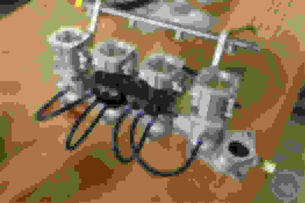
Yeah I can share it sometime. Probably when I get home to my computer tonight. It is an adapter for a Yamaha R6 set of throttles to an NB Miata flange. It is however a bit restrictive as the port size of the R6 is not big enough. But it still manages to put out 5-10 more whp and wtq. The R6 flange itself in the file is flipped 180* and won't line up (I had caught this mistake right when I was about to print it so I didn't save the final copy). I have the solidworks file though so if you want it to edit I can share it too). I am also in the process of printing another adapter for the R1 throttle body set which is pretty much a port-matched setup with the Miata port so I should get the real gains soon. But yeah 3D printing has been so handy. Instead of buying a $1,000 ITB setup I was able to make my own for $300 (literally everything that I needed).
Melvin is offline  
Old 01-21-2020, 12:00 PM
  #17  
Junior Member
 
Spaceman Spiff's Avatar
 
Join Date: Apr 2018
Location: Central Texas
Posts: 356
Total Cats: 93
Default

Originally Posted by shuiend
Mind sharing the stl? I would totally print one out for ***** and giggles on my CR-10.
If you ever want to do one for *****, giggles, and driving around I can get at this guy (https://markforged.com/mark-two/) and this guy (https://www.desktopmetal.com/products/studio) for just cost of materials.
Spaceman Spiff is offline  
Old 01-22-2020, 12:33 AM
  #18  
Junior Member
Thread Starter
 
Melvin's Avatar
 
Join Date: Oct 2018
Location: Glendora, CA
Posts: 201
Total Cats: -5
Default

Here it is. STL file, solidworks part file, and an NB intake port drawing.
Attached Files
File Type: zip
99-MIATA-INTK-FLANGE.zip (1.23 MB, 49 views)
Melvin is offline  
Old 01-22-2020, 06:52 AM
  #19  
Elite Member
iTrader: (5)
 
Stealth97's Avatar
 
Join Date: Oct 2007
Location: Canton, Ga
Posts: 2,156
Total Cats: 66
Default

You're actually driving around on a 3d printed manifold?
Stealth97 is offline  
Old 01-22-2020, 09:07 AM
  #20  
Junior Member
 
Spaceman Spiff's Avatar
 
Join Date: Apr 2018
Location: Central Texas
Posts: 356
Total Cats: 93
Default

Originally Posted by Stealth97
You're actually driving around on a 3d printed manifold?
All about those print settings and porosity.

We used to use a thin SLS manifold in SAE for that exact reason. Idled like ****, but you can get an extra 20% airflow past the restrictor by sucking air through the plastic
Spaceman Spiff is offline  


Quick Reply: Ideal Vacuum Pathway from ITBs to Block


All times are GMT -4. The time now is 08:06 PM.