
hey cable tee vee nerds and Joe Perez

Thread Starter


Joined: Jun 2005
Posts: 19,338
Total Cats: 574
From: Fake Virginia
Can I fashion a 75ohm terminator out of a short piece of coax w/connector and 75 ohms worth of resistor?
or do I even need one?
or do I even need one?
Reply
 0
0

0

Joined: Sep 2005
Posts: 34,424
Total Cats: 7,547
From: Chicago. (The less-murder part.)
or do I even need one?
Given the large number of vertical runs down into the top of that black rack, I'd guess that we are actually looking at an antenna switch, rather than the actual transmitter itself.
In the background (bottom-right of frame) is a patchbay (blue) of the sort usually used to switch a transmitter between the main antenna and a dummy load, or to select between one of two transmitters feeding an antenna, etc. This is slightly odd if my above is correct (that we're looking at the top of an antenna switch) as its presence would be rather redundant. It may be a remnant of an older configuration.
I've cut and brazed tons of that stuff. It's surprisingly easy to work with, given the size. You have to be pretty dead-on in your measurements (as the inners and outers are cut separately and to different lengths) however it's far easier than working with the "semi-flexible" stuff that's sometimes used to make weird bends. I'm a bit surprised to see that they are using slip-fit couplers with hose clamps, rather than brazed flanges. At high power levels, the line is usually filled with either nitrogen or dehydrated air (at very low pressure) to drive out moisture and prevent internal arcing. Its absence suggests that the transmitter building is climate-controlled. You can see a group of three pressure regulators on the back wall near the blue panel, and the connections into (out of?) that panel are flanged, so my guess would be that that panel is the final point before the line exits the building. (External lines are always pressurized.)
Reply
0
0

Reply
0
0
Thread Starter
Joined: Jun 2005
Posts: 19,338
Total Cats: 574
From: Fake Virginia
nicely done. I pulled that randomly from this page: http://hawkins.pair.com/wabcnow.shtml after seeing the flexible "hard line" and inflexible rigid line sections of the coax entry on wikipedia. who knew that TV was like plumbing?
Anyway.. back to my application...
I'm trying to fix a problem with my FiOS TV. Seems that Comedy Central HD (and subsequently the 2 new episodes of futurama that just aired) isn't coming in well. All (most?) other channels are great with no sign of macroblocking or audio dropouts.
The system runs up to somewhere around 900-950MHz for TV and above that for MOCA (fast internetz). Comedy Central HD shows up in the diagnostics screen on TiVo as 855000kHz so it's right up at the high end of the spectrum.
Google has shown links that suggest that installing a diplexer backwards -- essentially as a lopass filter (<950MHz) it helps to filter out any noise from the data stream. And thus the need for the terminator to cap the SAT port. I had already whipped up a cheapy one with a few resistors to get to 75ohms.
Sadly it didn't work.
But it's good to know that I made the terminator correctly.
Verizon's live chat tech told me to call and have Billing send me two new cablecards for some reason.
Apparently the macroblocking with Comedy Central HD is a frequent problem.
And it sucks!
Reply
0
0
Joined: Sep 2005
Posts: 34,424
Total Cats: 7,547
From: Chicago. (The less-murder part.)
No, it's actually pretty decent workmanship. Flanged connections are a lot of work to assemble, and those slip-fit joints are pretty common on indoor assemblies. You just have to control the humidity in the room. A lot of transmitter buildings, particularly those housing older tube-type machines, are not air-conditioned. In those environments, you'd expect to see either heliax or flanged connections.
Here's an example of the outer sleeve (this one is made by Myat):

And the bullet connector which is used to mate the inner conductors:
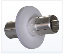
This is an example of a sealed, flanged connector (note the O-ring) into which moisture has nonetheless found its way:

And last but not least, Heliax. This is the "semi-flexible" cable which is used when you need to accommodate some degree of movement or make a weird bend. It is commonly used for the vertical runs up the side of a tower. Serious pain in the *** to terminate. Both the inner and outer are still solid copper, they're just slightly thinner and corrugated:

Here's an example of the outer sleeve (this one is made by Myat):
And the bullet connector which is used to mate the inner conductors:
This is an example of a sealed, flanged connector (note the O-ring) into which moisture has nonetheless found its way:
And last but not least, Heliax. This is the "semi-flexible" cable which is used when you need to accommodate some degree of movement or make a weird bend. It is commonly used for the vertical runs up the side of a tower. Serious pain in the *** to terminate. Both the inner and outer are still solid copper, they're just slightly thinner and corrugated:
Reply
0
0
Joined: Sep 2005
Posts: 34,424
Total Cats: 7,547
From: Chicago. (The less-murder part.)
nicely done. I pulled that randomly from this page: http://hawkins.pair.com/wabcnow.shtml after seeing the flexible "hard line" and inflexible rigid line sections of the coax entry on wikipedia.

who knew that TV was like plumbing?
But yeah, back when high-power VHF was just getting started, the first hardlines were manufactured by plumbing companies, using the same tooling they used to make water pipe. It is from this that the rather odd sizing conventions in use today for RF hardline were derived, and from whence came the now-ubiquitous 50 ohm standard (the first lines made from off-the-shelf plumbing pipe actually came in at around 52 ohms, I'm not sure when the transition to 50 was officially made.)
And there's the switch:

Reply
0
0

Takes me back to college. My EE101 professor is right when he told us the first week of class "Now, I know none of you are truly electrical engineers, so I'm going to teach you the minimum that you need to know to get by as a non-electrical engineer."
I'm impressed, and equally confused by this TV tube stuff.
I'm impressed, and equally confused by this TV tube stuff.
Reply
0
0


Reply
0
0
Thread Starter
Joined: Jun 2005
Posts: 19,338
Total Cats: 574
From: Fake Virginia
Reply
0
0
Joined: Sep 2005
Posts: 34,424
Total Cats: 7,547
From: Chicago. (The less-murder part.)
TV and radio both.
Actually, parts of it are quite easy. Prior to computerized control, transmitters were actually blindingly simple beasts. Here, for instance, is the complete schematic (including the power supply) of a Gates (Harris) FM3H, a twin-tube rig of early 1970s vintage:
I didn't omit anything- that really is the whole schematic for an FM transmitter the size of a refrigerator. Only the exciter (which does the actual audip-to-carrier modulation) is abstracted, as that is a separate unit.
But then it gets weird. Like, when you look at the output section, one of the first things you notice is that the antenna isn't actually connected to anything. Well, it's connected to ground through a capacitor, but that's it. It never actually touches the tube in any way:
And then you start looking around inside the RF cavity to locate the components. So, you see L2 and figure you're looking for a coil, right? Nope. It's a piece of copper pipe hanging in the middle of the cavity. You can move it around to coarse-adjust the tuning. The manual gives you a chart of how many inches away from the bottom of the PA cavity it's supposed to be for various frequencies. And don't get me started on L1- it's another piece of copper which is near the tube, but not touching it, that you can slide up and down to fine-tune the rig.
And the directional coupler? No, that's not at error. There really is a dead short at the far left end of it. You slide section FL2 in and out to set the length of the tee before the short, with the idea of putting it right at the second harmonic of the carrier.
Reply
0
0

Joe, you make me regret my choice to flunk out of college.
Y8s, I feel ashamed for how you have shamed yourself by being a cable TV subscriber. I thought that you were more progressive?
Y8s, I feel ashamed for how you have shamed yourself by being a cable TV subscriber. I thought that you were more progressive?
Reply
0
0
Thread Starter
Joined: Jun 2005
Posts: 19,338
Total Cats: 574
From: Fake Virginia
I got to get up close to a klystron used at the Stanford Linear Accelerator a few years back. Also got to lay my hand on the copper tube of one of their particle accelerators. they keep it behind some thick concrete doors. (probably keep it from interfering with someone's tv signal.... or cooking their ********)
so no ideas on my FiOS issue?
Reply
0
0
Joined: Sep 2005
Posts: 34,424
Total Cats: 7,547
From: Chicago. (The less-murder part.)
Physically, they sure are a sight to behold. This isn't a vacuum tube like most people are familiar with. Typically, they come mounted into a roll-around carriage and are simply wheeled into the transmitter and the cables and hoses attached. Heavy, too. There's always a winch mounted to the ceiling near the transmitter, so when you need to change the tube, you can hoist it up out of the trolley and lay it down into its original shipping container, then pick up the new tube out of the crate and drop it into position. (Tubes at this level aren't disposable- they get sent back to the manufacturer for rebuilding after they've exceeded their service life.)
This klystron is from the Canberra Deep Space Communications Complex, but it's similar to what you'd see in a typical high-power UHF transmitter:

so no ideas on my FiOS issue?
Reply
0
0

Thread
Thread Starter
Forum
Replies
Last Post


