
Hello from Turkey / İstanbul ,,, looking for technical help for non MiataCar


Thread Starter
Newb
Joined: Nov 2017
Posts: 5
Total Cats: 0
Hi,
My name is Emre Suat, I'm sorry that I could not afford a miata in turkey, but my heart is yours. I visit the forum year by year for DIY race preps and Aero modifications to learn something about going fast without too much engine power. I own an AlfaRomeo 159 1.9 JTDM. I know it is a diesel car. But it is good to have. 2 Years ago, it broke down with an engine failure. Oil mixed to Water. After That I want to rebuild it with twice the power without any smoke or any lag possible. And Also I want to challenge myself with this kind of goals. I searched lots of forums. Also I used to have workshop that help me with the engine modifications. After the Engine built. I did the rest of it. I made a billet intake manifold, Billet Exhaust manifold. a Custom Charge Cooler. With Custom HE, and pump from Merc. Almost all the engine compartment is changed. All of them is DIY. I learn from you also. About Turbo Placing and for the oil return of the Turbo, I learned lots of from this forum. But I'm in a place right now that my knowledge is lacking. And I need help.
Before I open a thread to "DIY Turbo" section. I want to ask you . . And I think you know lots of information about Charge cooling and Pumps and HE. All I need some information about them. Because other that low pressure gasoline engine. I want to cool high pressure Diesel. Like 3 Bars of Boost. With this 3 bars of boost you can imagine the post-Turbo Temperatures. it is about 265C degree. And I can only cool it down to 106C Degree in 35C degree ambient.
I'm lack of information about heating and Cooling. that's why I'm in trouble. . I'm Electrical engineer and This car is my hobby. It is helping me about learning lots of information about cars and diesel tuning.
I use Turbo from 350CDI , GTB2060VKLR, with original Electrical Actuator. It is VNT turbo with water cooled CHRA.
Normally, my friends suggested that I use Air2Air intercooler for this setup. But I wanted to challenge myself. And tried Water 2 Air intercooler. One of my friend is tuning only Mercs in Turkey. He suggested that I use a bosch pump, 0392 022 010 .
With an uninterested tuner from Turkey, I get 260HP and 550Nm torque , with 104 Degree Celc IAT . Now as you can imagine I'm having some IAT problems. I think there is something about HE capacity. I don't know yet. I've tried to search the forum, I found very useful information. But I could not ask you before. And I don't know where to start? In which area should I ask for help. Or Do I have permission to ask in first place?..
IN = Post Turbo , ChargeCooler Inlet Temp
OUT = ChargeCooler Outlet Temp , aka IAT
WIN = WaterInlet Temp of ChargeCooler
WOt = WaterOutlet Temp of ChargeCooler
EGT = EGT But this is in the Turbo exit . Inside the Downpipe
CP: Chip Temperature, inside the bonnet. I want to see that closed case temp. controller chip temperatures I don't want to burn them....
My name is Emre Suat, I'm sorry that I could not afford a miata in turkey, but my heart is yours. I visit the forum year by year for DIY race preps and Aero modifications to learn something about going fast without too much engine power. I own an AlfaRomeo 159 1.9 JTDM. I know it is a diesel car. But it is good to have. 2 Years ago, it broke down with an engine failure. Oil mixed to Water. After That I want to rebuild it with twice the power without any smoke or any lag possible. And Also I want to challenge myself with this kind of goals. I searched lots of forums. Also I used to have workshop that help me with the engine modifications. After the Engine built. I did the rest of it. I made a billet intake manifold, Billet Exhaust manifold. a Custom Charge Cooler. With Custom HE, and pump from Merc. Almost all the engine compartment is changed. All of them is DIY. I learn from you also. About Turbo Placing and for the oil return of the Turbo, I learned lots of from this forum. But I'm in a place right now that my knowledge is lacking. And I need help.
Before I open a thread to "DIY Turbo" section. I want to ask you . . And I think you know lots of information about Charge cooling and Pumps and HE. All I need some information about them. Because other that low pressure gasoline engine. I want to cool high pressure Diesel. Like 3 Bars of Boost. With this 3 bars of boost you can imagine the post-Turbo Temperatures. it is about 265C degree. And I can only cool it down to 106C Degree in 35C degree ambient.
I'm lack of information about heating and Cooling. that's why I'm in trouble. . I'm Electrical engineer and This car is my hobby. It is helping me about learning lots of information about cars and diesel tuning.
I use Turbo from 350CDI , GTB2060VKLR, with original Electrical Actuator. It is VNT turbo with water cooled CHRA.
Normally, my friends suggested that I use Air2Air intercooler for this setup. But I wanted to challenge myself. And tried Water 2 Air intercooler. One of my friend is tuning only Mercs in Turkey. He suggested that I use a bosch pump, 0392 022 010 .
With an uninterested tuner from Turkey, I get 260HP and 550Nm torque , with 104 Degree Celc IAT . Now as you can imagine I'm having some IAT problems. I think there is something about HE capacity. I don't know yet. I've tried to search the forum, I found very useful information. But I could not ask you before. And I don't know where to start? In which area should I ask for help. Or Do I have permission to ask in first place?..
IN = Post Turbo , ChargeCooler Inlet Temp
OUT = ChargeCooler Outlet Temp , aka IAT
WIN = WaterInlet Temp of ChargeCooler
WOt = WaterOutlet Temp of ChargeCooler
EGT = EGT
But this is in the Turbo exit . Inside the DownpipeCP: Chip Temperature, inside the bonnet. I want to see that closed case temp. controller chip temperatures I don't want to burn them....
Reply
 0
0

0
Your post says that:
I am assuming the "chargeCooler" is the heat exchanger that is cooling the boosted/heated air? If so, then the waterOutlet temp should be higher than the waterInlet temp, but that was not the case in your video. Do you have those sensors backwards?
If the sensors are backwards, and your water_in temp is 47, water_out is 62, and AIT is 104, your charge air cooler is not very effective as it's getting a good supply of coolant, but not exchanging as much heat as it could.
Also 245C is 473F, which is insanely hot. I would upsize the chargeCooler, retest, and then perhaps upgrade the pump if the new larger charge air cooler requires more flow to take advantage of the increased cooling capacity.
IN = Post Turbo , ChargeCooler Inlet Temp
OUT = ChargeCooler Outlet Temp , aka IAT
WIN = WaterInlet Temp of ChargeCooler
WOt = WaterOutlet Temp of ChargeCooler
OUT = ChargeCooler Outlet Temp , aka IAT
WIN = WaterInlet Temp of ChargeCooler
WOt = WaterOutlet Temp of ChargeCooler
If the sensors are backwards, and your water_in temp is 47, water_out is 62, and AIT is 104, your charge air cooler is not very effective as it's getting a good supply of coolant, but not exchanging as much heat as it could.
Also 245C is 473F, which is insanely hot. I would upsize the chargeCooler, retest, and then perhaps upgrade the pump if the new larger charge air cooler requires more flow to take advantage of the increased cooling capacity.
Reply
0
0


With that large a difference between the charge air temperature and ambient an air to air intercooler will be very effective. There is a reason OEM manufacturers use them. They are effective, simple, and inexpensive.
We have a senior member of this forum in Istanbul that may be good to talk to. @Godless Commie might offer some assistance.
We have a senior member of this forum in Istanbul that may be good to talk to. @Godless Commie might offer some assistance.
Last edited by sixshooter; Nov 19, 2017 at 08:14 AM.
Reply
0
0
Thread Starter
Newb
Joined: Nov 2017
Posts: 5
Total Cats: 0
Your post says that:
I am assuming the "chargeCooler" is the heat exchanger that is cooling the boosted/heated air? If so, then the waterOutlet temp should be higher than the waterInlet temp, but that was not the case in your video. Do you have those sensors backwards?
If the sensors are backwards, and your water_in temp is 47, water_out is 62, and AIT is 104, your charge air cooler is not very effective as it's getting a good supply of coolant, but not exchanging as much heat as it could.
Also 245C is 473F, which is insanely hot. I would upsize the chargeCooler, retest, and then perhaps upgrade the pump if the new larger charge air cooler requires more flow to take advantage of the increased cooling capacity.
There is 4LT fluid. And Pump has 0.5lt / Sec flow capacity.
Charge cooler capacity is 4Lt , and Front Radiator has 3.7Lt capacity....
With that large a difference between the charge air temperature and ambient an air to air intercooler will be very effective. There is a reason OEM manufacturers use them. They are effective, simple, and inexpensive.
We have a senior member of this forum in Istanbul that may be good to talk to. [Utag]Godless Commie[/utag] might offer some assistance.
We have a senior member of this forum in Istanbul that may be good to talk to. [Utag]Godless Commie[/utag] might offer some assistance.
He is the one for me... I've read almost all of the thread that he opened in Turkey. And after that I decided to do my DIY projects... I will talk to him of course. But Before I call him, I need to get /find information.....
But Thank you anyway....
PS: In MercedesBenz Forums... They said. Front radiator is not Big enough for the cooling capacity. Because Core: "Charge Cooler" can cool this kind of hot air. But If there is cold water supply. They also give too many information and it confused me...
They Said Front radiator is for Car Engine Cooling. It has High Pressure, High Flow system.... that's why It does not cool my fluid mix for the intercooler. I used dual pass on that radiator. Maybe this is putting pressure for the system. And it lowers the flow....
Reply
0
0
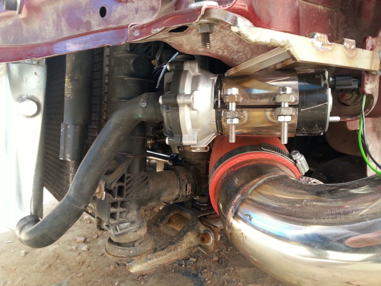
Please draw a diagram showing the route of the intake air and location of the coolers. I have great difficulty picturing the route and systems from the video and descriptions.
Are you putting the hot exhaust out right in front of the coolers? That is not helping.
Godless Commie's name is Hakan. He's a TV star on the Turkish version of Junkyard Wars, but I don't know what they call it.
Are you putting the hot exhaust out right in front of the coolers? That is not helping.
Godless Commie's name is Hakan. He's a TV star on the Turkish version of Junkyard Wars, but I don't know what they call it.
Reply
0
0
Thread Starter
Newb
Joined: Nov 2017
Posts: 5
Total Cats: 0
Here is some drawings. And you are right about Mr Hakan, He is now a star in TV, that all the petrolheads are watching his show.


Cooler in the Engine

Pump Location
Turbo has different Compressor Wheel. It has GTX 2.GEN 10+0 .
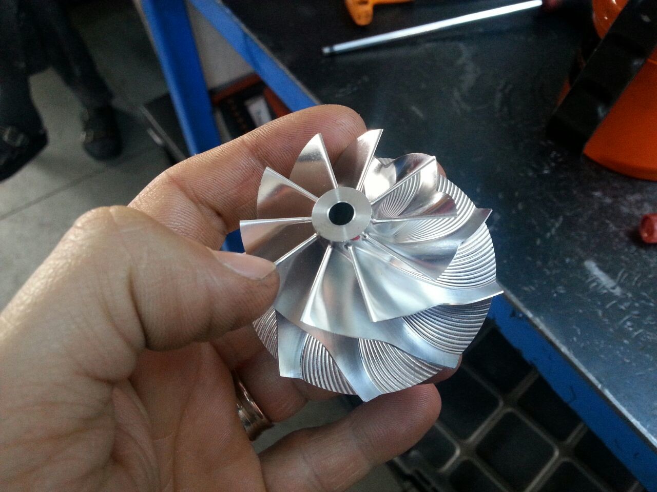
Cooler in the Engine
Pump Location
Turbo has different Compressor Wheel. It has GTX 2.GEN 10+0 .
Reply
0
0
ChargeCooler connected between Turbo And Intake Manifold. Heat Exchanger is in front trying to cool the water/antifreeze mix. But Maybe In this video I did not check the waterIN or waterOUT sensor. But I was sure that I connected them correct. In this setup.
There is 4LT fluid. And Pump has 0.5lt / Sec flow capacity.
Charge cooler capacity is 4Lt , and Front Radiator has 3.7Lt capacity....
Thank you for the advise. And I think it looks like I know "Godless Commie", I've talked to him on the phone about something else. Another DIY project for Lower Front Suspension Arm for Alfa Romeo.
He is the one for me... I've read almost all of the thread that he opened in Turkey. And after that I decided to do my DIY projects... I will talk to him of course. But Before I call him, I need to get /find information.....
But Thank you anyway....
PS: In MercedesBenz Forums... They said. Front radiator is not Big enough for the cooling capacity. Because Core: "Charge Cooler" can cool this kind of hot air. But If there is cold water supply. They also give too many information and it confused me...
They Said Front radiator is for Car Engine Cooling. It has High Pressure, High Flow system.... that's why It does not cool my fluid mix for the intercooler. I used dual pass on that radiator. Maybe this is putting pressure for the system. And it lowers the flow....
Reply
0
0
Thread Starter
Newb
Joined: Nov 2017
Posts: 5
Total Cats: 0
If the water out of the charge cooler is 62*C, and air is 104*C, that's a 42*C difference, or 75*F difference which is quite a bit. But I think the high air inlet temp is a big part of the problem as that heat exchanger is getting slammed with a ton of heat. Given the charge cooler is getting 47*C water still, that means the front radiator is cooling the charge water pretty well. Needs bigger charge cooler.

Reply
0
0
The air to water cooler looks very small for the amount of heat you are trying to remove.
And it also looks like it doesn't flow as much air volume as the inlet pipe.
What I originally thought was exhaust is actually a can for the air filter element.
Consider making a much longer air to water cooler across the engine compartment between the valve cover and the radiator and/or maybe adding a remote mount air to air cooler somewhere else on the car if you are making so much heat. Heat is the enemy of power. Just running an air pipe to the rear under the car and back to the front would help lose the heat, even better with an intercooler back there somewhere. You are very creative. Continue to think in innovative ways. Have you seen the Miata with the radiator in the trunk? I'm not saying put yours there but it is an interesting solution.
Reply
0
0
One of My Mercedes Guy, who is expert on Charge Cooling. He only suggest / told me that : " Use dual pass on ChargeCooler. You are using single pass. If you would used second pass on this cooler. It will get you at least %30 more cooling capacity" But it was after I welded the cooler
I think the layout is ok, the cooler just needs to be upsized to cope with the amount of heat it's getting. That or as suggested, put a small air/air heat exchanger before the water/air charge cooler. I'm a mechanical engineer by education.
Reply
0
0
Thread Starter
Newb
Joined: Nov 2017
Posts: 5
Total Cats: 0
Hello again.
I want to share all the information that I've found from anybody.
Hi Emre,
You've done some very nice work there. Those end tanks look extraordinary. Did you make them? Did you make the inlet manifold as well?
That radiator looks like a good heat exchanger, but are you sure the matrix is only 16 mm thick - that's typical for AC condensers? That's not an uncommon size, but it does look a bit thicker than that.
I notice that you have the pump mounted horizontally, low down, and at the outlet of the HE, which is all good. It's essential that you get all the air out of the IC system, and it looks like you have a swirl pot to ensure that.
Your system is ambitious, so the Bosch pump is the MINIMUM you should be considering. Popular options like the Johnson CM30 should NEVER be considered for IC's.
The first thing I would suggest is uprating the pump. The Pierburg CWA-50 or 100 is the obvious first place to go (it's what all the manufacturers use these days). Alternatively you could add a second Bosch pump in series in the circuit.
Considering how much resource you're putting into this, I'd suggest going the whole hog and get an EMP WP29 pump instead. More expensive, but absolutely the best.
The only other think you could do, and I'm sure it would be very worthwhile, is to increase the size of the water pipes from 3/4" to 1" or more.
All the best, Nick
Hello again,
Thank you very much for the compliment Yes I did all the parts by myself. All of them has flow simulations. And tested. But you know the real world is different. I cannot put all the variables to the simulations. So It gave me not false results but near results. I have to think and execute logic to get a better result.
The radiator matrix is about 16mm yes. It is and engine radiator from Dacia Logan 1.6 petrol Engine. So it is designed to work with an engine pump and flow. Maybe that's why It does not work in my setup. But the End Case was designed by me. And It is 52mm inside diameter. I was suggested that I use bigger End Cases to have more fluid in front of the engine.
All the pumps are great but I can change the front radiator, It is easy for me to do. When I design this setup. I was afraid of the placement of the front radiator but. Now I can fit. like 10cm longer radiator to the front. And up to 55mm thickness I can design to the matrix of the radiator.
If I'm not wrong I think this thin radiator should be used with high pressure water pump. And that's why you recommend me one of them. Only for the knowledge of this kind of setup. I want to go with thicker radiator. that I think it will lower my pressure drop. Does it help?
My friend recommend me, before you wrote it. If we lower the pressure drop, it will speed up the water. And It's a good thing. Also 4lt total water capacity is low. Maybe we can double or triple it. And for the pump. It is sucking from under the HE. Lets put it under the water Tank. It is suck easier than HE. maybe this would help a little.
I don't want to be looking like I resist your pump advice here. Because of our greedy government our import taxes are very high. In Turkey it is a thing. Your advised pump is almost 2.5 times expensive in Turkey right now. So that's why I went other directions. Maybe second serial pump is a good thing. Also I have a VW Tsi engine water pump. Small like a Fist. I had bought two of them. And My older idea was to use them in parallel to keep the flow. But then I've read this forum. And My whole ideas changed First I did not had time. Because I had to get this car going, because It was 1 year he was sleeping. And I have to give my spare car back to my dad.
Anyway. Thank you for the advise
Also I've realised that maybe I'm not using the whole Core. Core means the Air2Water Core. I will upload them soon. Because of the 90 degree silicone bends, flow does not want to share whole 14cm x 14cm area. I think I will using almost half of it. So its a bad thing right ?
I want to share all the information that I've found from anybody.
Hi Emre,
You've done some very nice work there. Those end tanks look extraordinary. Did you make them? Did you make the inlet manifold as well?
That radiator looks like a good heat exchanger, but are you sure the matrix is only 16 mm thick - that's typical for AC condensers? That's not an uncommon size, but it does look a bit thicker than that.
I notice that you have the pump mounted horizontally, low down, and at the outlet of the HE, which is all good. It's essential that you get all the air out of the IC system, and it looks like you have a swirl pot to ensure that.
Your system is ambitious, so the Bosch pump is the MINIMUM you should be considering. Popular options like the Johnson CM30 should NEVER be considered for IC's.
The first thing I would suggest is uprating the pump. The Pierburg CWA-50 or 100 is the obvious first place to go (it's what all the manufacturers use these days). Alternatively you could add a second Bosch pump in series in the circuit.
Considering how much resource you're putting into this, I'd suggest going the whole hog and get an EMP WP29 pump instead. More expensive, but absolutely the best.
The only other think you could do, and I'm sure it would be very worthwhile, is to increase the size of the water pipes from 3/4" to 1" or more.
All the best, Nick
Hello again,
Thank you very much for the compliment
Yes I did all the parts by myself. All of them has flow simulations. And tested. But you know the real world is different. I cannot put all the variables to the simulations. So It gave me not false results but near results. I have to think and execute logic to get a better result.The radiator matrix is about 16mm yes. It is and engine radiator from Dacia Logan 1.6 petrol Engine. So it is designed to work with an engine pump and flow. Maybe that's why It does not work in my setup. But the End Case was designed by me. And It is 52mm inside diameter. I was suggested that I use bigger End Cases to have more fluid in front of the engine.
All the pumps are great but I can change the front radiator, It is easy for me to do. When I design this setup. I was afraid of the placement of the front radiator but. Now I can fit. like 10cm longer radiator to the front. And up to 55mm thickness I can design to the matrix of the radiator.
If I'm not wrong I think this thin radiator should be used with high pressure water pump. And that's why you recommend me one of them. Only for the knowledge of this kind of setup. I want to go with thicker radiator. that I think it will lower my pressure drop. Does it help?
My friend recommend me, before you wrote it. If we lower the pressure drop, it will speed up the water. And It's a good thing. Also 4lt total water capacity is low. Maybe we can double or triple it. And for the pump. It is sucking from under the HE. Lets put it under the water Tank. It is suck easier than HE. maybe this would help a little.
I don't want to be looking like I resist your pump advice here. Because of our greedy government our import taxes are very high. In Turkey it is a thing. Your advised pump is almost 2.5 times expensive in Turkey right now. So that's why I went other directions. Maybe second serial pump is a good thing. Also I have a VW Tsi engine water pump. Small like a Fist. I had bought two of them. And My older idea was to use them in parallel to keep the flow. But then I've read this forum. And My whole ideas changed
First I did not had time. Because I had to get this car going, because It was 1 year he was sleeping. And I have to give my spare car back to my dad. Anyway. Thank you for the advise
Also I've realised that maybe I'm not using the whole Core. Core means the Air2Water Core. I will upload them soon. Because of the 90 degree silicone bends, flow does not want to share whole 14cm x 14cm area. I think I will using almost half of it. So its a bad thing right ?
Reply
0
0


