
**Reward for getting my spark working**


Thread Starter
Junior Member
iTrader: (2)
Joined: Sep 2008
Posts: 174
Total Cats: 0
From: Sandy, Utah
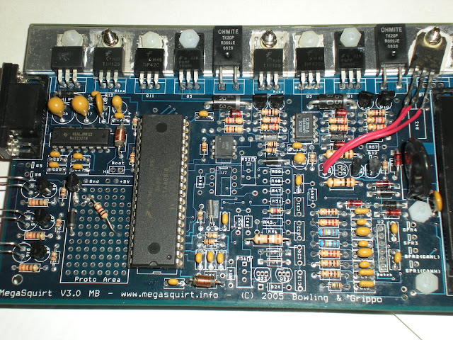
I have built a MS-1 V3 per Braineack's instructions. I am all done with construction including idle and fan mods. I have the firmware and MSPNP 95 w/o AFM base map installed.
I am getting no response on the ignition LEDs, nor on the stim. I am a strong believer in free-market economics and fair trade for knowledge and labor. Along these lines I am offering $20 or a perfectly functional BIPES unit to the person who helps me solve this ($20 by paypal - or free shipping if that person chooses the BIPES. If multiple people have the correct answer, the first with the answer gets the prize).
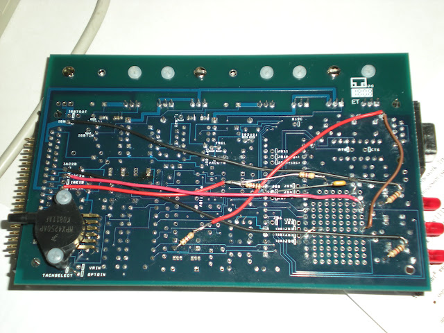
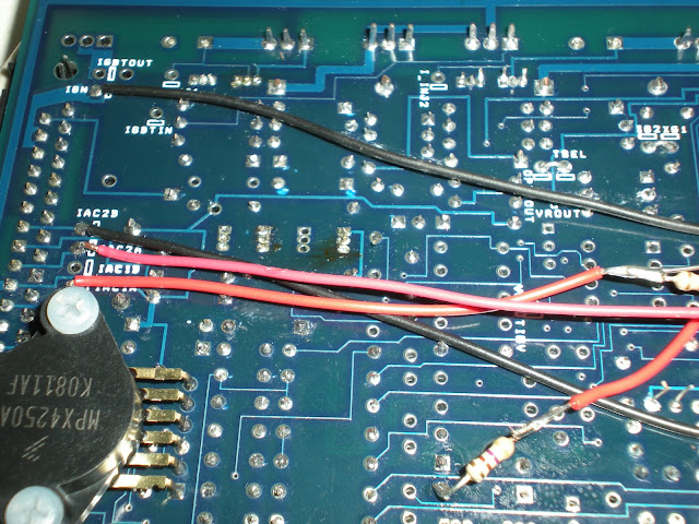
I will upload pics of the front and back of the board as well as the .msq. The only thing I changed from the MSPNP map is the MAP sensor I believe.
I have washed the board in acetone and have looked as closely as I can at the solders. I can't see anything wrong.
I really want to get this working. Ideally - someone will take a look at the pics and say ****ing noob! you forgot to jump XXX and XXX. - that's still worth giving out the money or bipes imo.
Thanks in advance to any help!
I am getting no response on the ignition LEDs, nor on the stim. I am a strong believer in free-market economics and fair trade for knowledge and labor. Along these lines I am offering $20 or a perfectly functional BIPES unit to the person who helps me solve this ($20 by paypal - or free shipping if that person chooses the BIPES. If multiple people have the correct answer, the first with the answer gets the prize).
I will upload pics of the front and back of the board as well as the .msq. The only thing I changed from the MSPNP map is the MAP sensor I believe.
I have washed the board in acetone and have looked as closely as I can at the solders. I can't see anything wrong.
I really want to get this working. Ideally - someone will take a look at the pics and say ****ing noob! you forgot to jump XXX and XXX. - that's still worth giving out the money or bipes imo.
Thanks in advance to any help!
Reply
 0
0

0
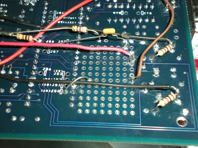
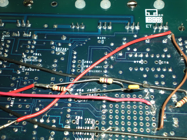
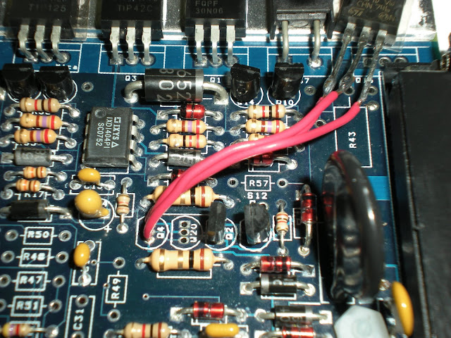
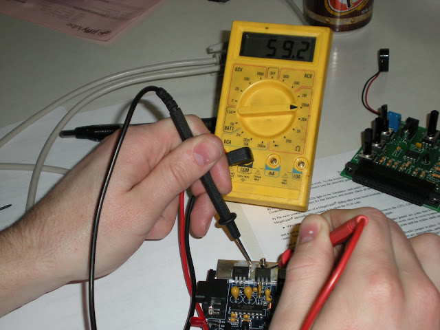
Check the resistances on all the transistors that should have insulators. Specifically Q9 and Q12. Those should have nylon screws and insulators, yours have steel screws. Resistance from the base of those to the metal bar should be like 50M ohms or something. It's in the megamanual, like step 63ish IIRC.
Reply
0
0

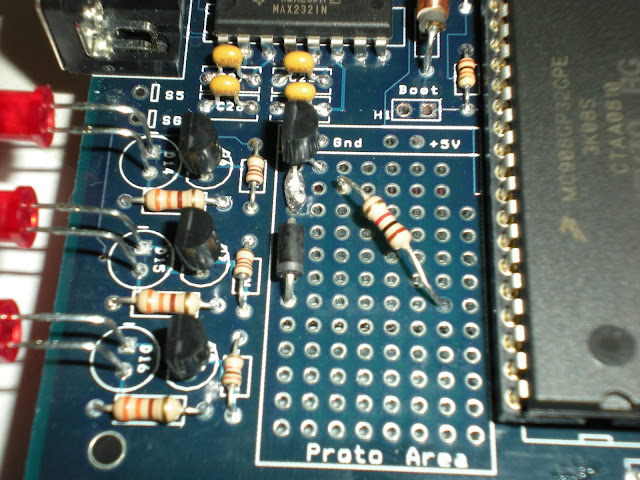
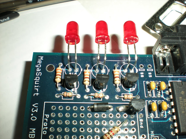
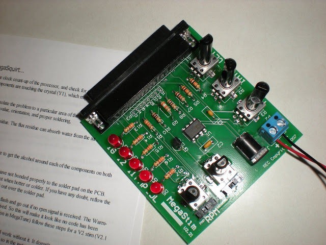
you have the LEDs installed backwards. that is why they arnt lighting.(i did this too)
you may have the wrong stim is it the JIM stim ? or the regular stim the regular one will not work with the Miatas Ignition mods.(did this too)
The LEDs Are constantly lit for me because the system acts so quick. The middle is for Cold start enrichment.
you may have the wrong stim is it the JIM stim ? or the regular stim the regular one will not work with the Miatas Ignition mods.(did this too)
The LEDs Are constantly lit for me because the system acts so quick. The middle is for Cold start enrichment.
Reply
0
0
Thread Starter
Junior Member
iTrader: (2)
Joined: Sep 2008
Posts: 174
Total Cats: 0
From: Sandy, Utah
you have the LEDs installed backwards. that is why they arnt lighting.
you may have the wrong stim is it the JIM stim ? or the regular stim the regular one will not work with the Miatas Ignition mods.
The LEDs Are constantly lit for me because the system acts so quick. The middle is for Cold start enrichment.
you may have the wrong stim is it the JIM stim ? or the regular stim the regular one will not work with the Miatas Ignition mods.
The LEDs Are constantly lit for me because the system acts so quick. The middle is for Cold start enrichment.
Would backwards LEDs actually kill the spark? I wouldn't think so. I did try to actually put it in the car, and I get no spark at the plugs.
(Coils are still good as car runs fine with factory ECU reinstalled.)
Reply
0
0
I would put them in right and try it again.
Reply
0
0
I think you have your LED's in backwards. 99% sure, I'm looking for a better pic of how they should be. You should also see 60M ohms, not 60k ohm. Need to fix that for sure.
Reply
0
0


Reply
0
0
 Those LED's are your spark outputs. So if they're backwards, you will have no spark. I did the same thing a long time ago and had a tach signal but no spark. Swapped my LED's and it worked.
 Also work on your soldering a bit. You want to go fast-hard-short when soldering. Some of the joints on your board are not ideal.
Reply
0
0
Reply
0
0
But its w/e.
Reply
0
0

Also, since no one told him why they can tell the LEDs are backwards - see the little line on the board where the LEDs go? That symbol means you put the flat side of the diode on that side (can't remember if it is the anode or cathode, it has been 12 years since my last electronics class).
Reply
0
0


