When you click on links to various merchants on this site and make a purchase, this can result in this site earning a commission. Affiliate programs and affiliations include, but are not limited to, the eBay Partner Network.
[HELP?]DIY MS2 - Last checks before dropping it in the car - It runs!-ish
Hello Guys,
I think I've pretty much finished my DIY MS2. (I know, MS3, PNP, blah blah, but I already had it, purchased in 2013 with my Bitcoin mining from 2009, so, basically free).
I'm using the VR circuit and the Opto Circuit for the RPM inputs as well as the TC4427 for the output.
I have a DIYBOB from the rusEFI guys from which I'm pulling all the wires to the MS2 and I think I miiiiight want to run inputs only for a while until I can log what kpa, temps, etc is the stock ECU running around.
I'll be running the GM IAT and hopefully removing the AFM, and I'll be fitting a BMW TPS on the stock TB to have VTPS as well,I just need to make an adapter plate so I can keep the stock TPS in a box in case I want to roll back.
Anyway, I have some questions about the TIP120 for the PWM.
I found two different circuits which might actually be the same thing but I'm not positive on that.
One is just replacing Q4 with the TIP120 as in this pic:
This is what I did. Says to later put a diode across the PWM valve, which I haven't done yet.
But later I found this:
And now I'm confused. I understand that the latter includes the diode on the board instead of at the PWM valve, but it doesn't look like the same circuit to me. Which one should I be using?
If I wanted to share sensors with the stock ECU to get an initial reading and perhaps let it handle the IDLE, are there any resistor add/removals I should do? I believe that I should remove R4 and R7? I found some info for MS1, but not for MS2, so unsure.
And last. Since I don't use CAN, and I don't have EBC yet, could it be possible to run the A/C through the MS2 and control it with a programable output? Any mods required for that? I think that perhaps I can control the idle better that way by giving the PWM some extra duty to compensate.
I know that normally you connect 1J and 1Q at the connector, does that help with the idle or just "forwards the signal" to the A/C clutch?
I really appreciate your help and hopefully I can start playing around with this and sharing my results!
Thanks!
Last edited by Nicolas L; Mar 13, 2017 at 07:15 AM.
they are exactly the same circuit, but the bottom one is using stronger power and ground points than the Q4 holes. the middle Q4 hole is the idle signal from the CPU.
the 1n4001 is required for both methods.
for a/c in:
wire the a/c switch to the harness into one of the spare inputs either SPARE 1-4, or any available IAC hole. Inside the Ms, youll run that wire to a simple input circuit (built in proto area) and finally into one of the spare JS holes (like JS7)
so like this:
for a/c out:
you'll wire the output signal from one of the spare JS holes form the CPU, to a simple output circuit (again in proto) and send it out to the harness via one of the spare IAC holes, and wire that to your a/c compressor relay.
you can also wire the a/c fan to this, or build another circuit to handle that directly.
you'll have to double check the firmware and manual, which JS pins you can use.
That's awesome! I'll get on building that right now. I happen to have some spare 1N4005s laying around.
Thank you Braineak! I'll post pictures of my ghetto board when I'm done. It looks like **** because I tried to remove the flux with alcohol but it just smeared it all over the board hahah.
And I didn't have 15R resistors for the output of the spark so I put a 22R and a 47R in paralel for the output, looks like **** but I get 14,9R, close enough.
Alright, getting ready to see if I can plug this in tomorrow.
I'm going to get a vacuum hose to route the MAP input tomorrow and I'm wondering what else needs to be done.
This is just to see if I can get the car to start and measure the timing, I'll unplug it right after because it's my daily and I guess on Monday after work I'll see if I can dig further.
-Can I run it at first with the AFM plugged in and change the air temp sensor values to the AFM? If I do this I should disconnect the FP Out of the MS2 right?
-If I unplug it and connect the Fuel Pump pins in the AFM plugs and run the MS Fuel Pump Out (purple cable) to the pin 2O, do I need to remove the fuse as the PNP guys?
Anything else I need to get ready in the car to check for initial startup without blowing any fuses or burning any components of my board?
with the AFM in place, you dont need to run the FP wire--the AFM activates the FPR when the flapper is sucked open. 2O is the AFM Signal wire, so having that in place now, won't do anything detrimental in the AFM is still in place -- you've removed the 5v power wire on 2K so you won't be causing any shorts.
When you remove the AFM, you must jump 2O with the FPR pin on the connector itself.
You do not need to pull any fuse when you control the fuel pump in this manner.
Wonderful. I haven't had a chance to test this because apparently there is something wrong with my brain that I've been trying to figure out but as soon as I get my balance under control again I'll just plug this **** in and see if I can get any signal!
with the AFM in place, you dont need to run the FP wire--the AFM activates the FPR when the flapper is sucked open. 2O is the AFM Signal wire, so having that in place now, won't do anything detrimental in the AFM is still in place -- you've removed the 5v power wire on 2K so you won't be causing any shorts.
When you remove the AFM, you must jump 2O with the FPR pin on the connector itself.
You do not need to pull any fuse when you control the fuel pump in this manner.
I just found a very detailed pinout and I'm trying to get every bit of information in place and match it with what I have.
I noticed that you mentioned 2K but I didn't really know what 2K did at the time.
It looks like it's 5V to the AFM connector.
You said "you removed the 2K wire", but it's just not going anywhere. I'm assuming the power source for that 5V came from the stock ECU and therefore since I'm not plugging the stock ECU in the circuit there won't be any power at 2K, correct?
I'm plugging this baby in today, I haven't created the A/C circuit because I'm planning on how I'm going to place all the components in the proto area along with the clutch input, but I wanted to see if at least I can get a clean spark signal into the MS.
Pros:
My BMW TPS seems to be plugged in fine, didn't have to rewire anything.
CLT and AIT look fine, 2-3 degrees of difference between them but I haven't put the GM AIT yet.
My Daughterboard did not explode.
There wasn't any fires because of my boomslang!
On the other hand, I get NO input signal whatsoever. Nada. The log is empty. Engine speed at 0.
So, now that's where I have to start looking. I'm trying to see if I can get signal IN, I'll worry about the outs later.
My input follows this:
5.2.3
a) Solder a link between VRIN and TACHSELECT
b) Solder a wire between VrOUTInv and TSEL
c) Install a 1k resistor (any value 470R - 2k2 is likely OK) in the proto area. Connect one end to the 5V hole and
join the other end to VRIN with a jumper wire.
d) With a small screwdriver, turn the pots, R52 and R56, about 12 turns anticlockwise (sometimes you may feel
a "click" when the end position is reached, they can't be damaged by turning too far.) and then turn R56 back
about 6 turns clockwise.
5.2.14.2 Adding a cam sensor input - hall sensor / optical sensor
This option uses the spare opto-isolator on the mainboard for the cam input and matches the polarity inversion
of the VR/universal tach input.
This section is for open-collector sensors as covered in 5.2.3 that ground switch only.
a) The OptoIn pad should be connected to a spare pin on the main DB37 connector (e.g. SPR3)
b) Connect OptoOut to JS10 (ensuring that nothing else is connected.)
c) Jumper XG1 - XG2
d) Check that R12 is a 390R to 470R resistor, replace if not.
e) Install a 470R 1/4W resistor on the proto area to +5V.
f) Jumper the other end of the 470R resistor to OptoIn (joining the jumper wire there.) I have to the top of C30, same **** according to the diagram below.
g) Ensure that C30 is not fitted.
The one below is Braineak's circuit map which I THINK it's pretty much the same but the pullups go to 5v instead of 12v, right? Shouldn't I be getting SOME signal anyway? I tried falling edge or rising edge and didin't get jack ****.
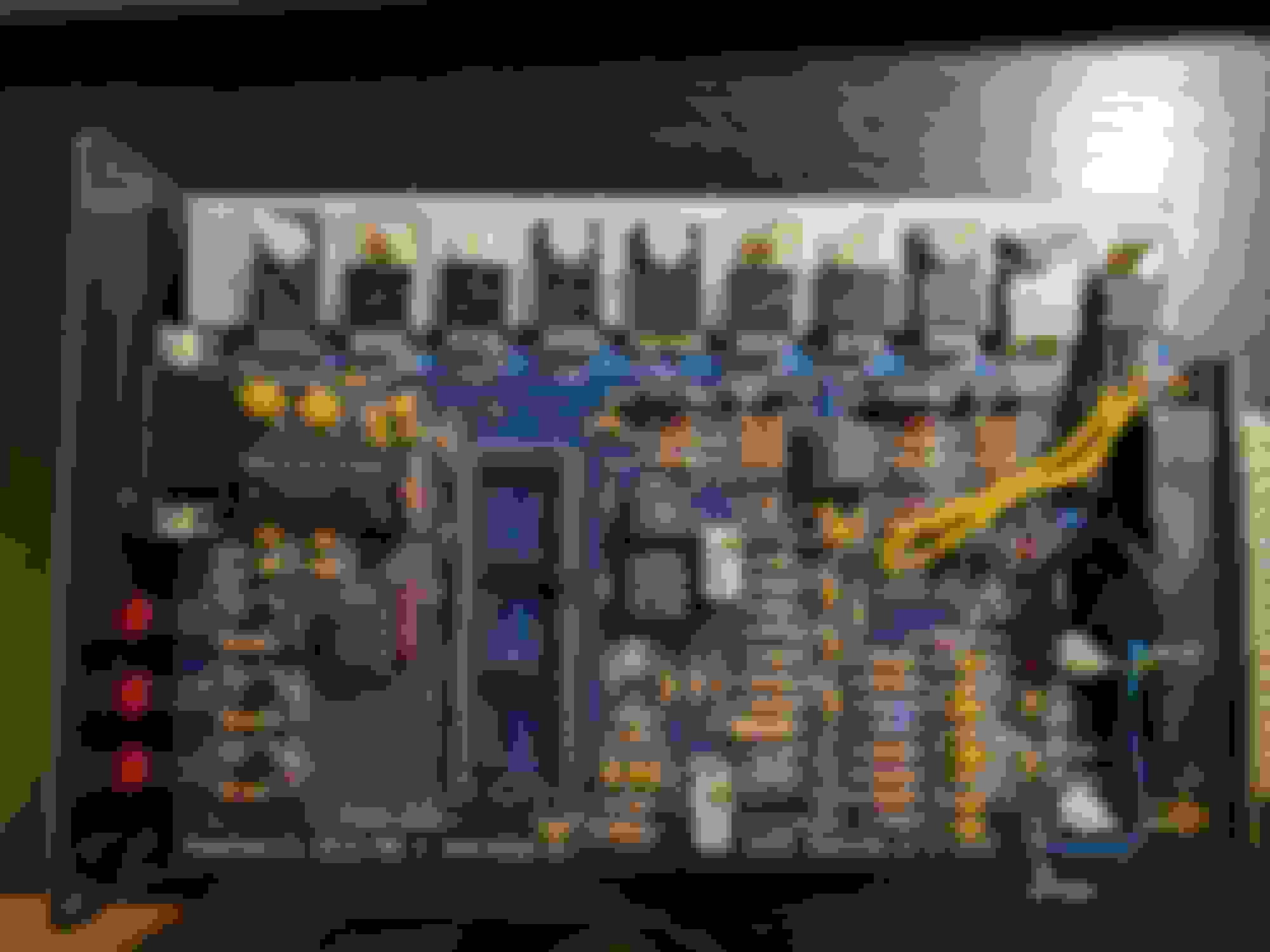
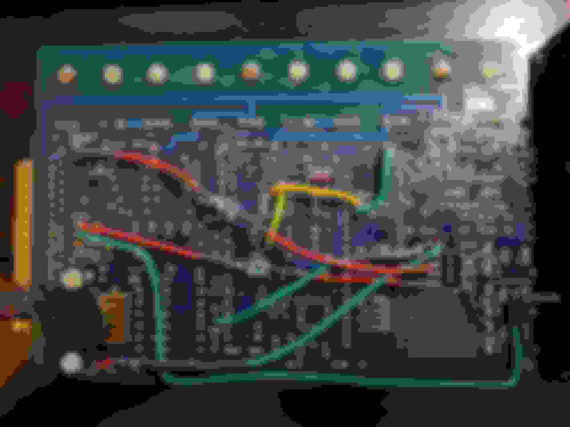
And these are the pictures of my board (Pardon the appearance, it has seen some **** along the years, and the flux is smeared everywhere).
OPTOIN to IAC1A.
GND and 5V supply to TC4427 TACHSELECT <-> VRIN
VRIN <-1K -> 5V
TSEL - VROUTINV
OPTOOUT - JS10
S12C - JS9
I THINK I got it right but I'm going to have to review this bitch now.
I'll keep you posted
Last edited by Nicolas L; Mar 11, 2017 at 09:26 PM.
You said "you removed the 2K wire", but it's just not going anywhere. I'm assuming the power source for that 5V came from the stock ECU and therefore since I'm not plugging the stock ECU in the circuit there won't be any power at 2K, correct?
correct.
you didnt have to search for one... you could just ask...
you didnt have to search for one... you could just ask...
Well I rather do my homework first
Originally Posted by Braineack
whats in your proto area?
A TC4427, I'm using that for my outputs.
My only concern is that I followed the msextra manual that says to connect the inputs of the TC to the R26 and R29, but I see that your output uses the LED as outputs. So going to the resistors I DON'T have the spark out going low, I have it going high. Is this something that I should change? I measured the pins going OUT and while the MS is just sitting I have the LEDs OFF and 0V on the output, basically it follows the LED state to the output.
Aaaand I managed to get RPM!
First my wiring was wrong, somehow I mixed Tach in with IAC1B.
After that I still wasn't getting **** so I worked around with the settings, no dice.
I adjusted the VR conditioner until I had 2.5xV on top of R57(or R54? the one next to the variable resistor).
I still had some random **** showing up and nothing was syncing. I played with rising/falling edge and I would get some random engine speed readings but not consistent, it would jump to 150 then 0, then 200, 0 ,etc/
Until I changed the cam polarity to INVERTED and BAM, magic.
Now I don't remember if I have it as falling or rising edge but I'll get some screenshots of what I have once I get it running in case people in the future wants to follow my steps.
I have NOT run anything from it yet, I just want to make sure I have the inputs right, and I'm working incognito in my parking lot because the HOA doesn't allow any kind of car related work lol.
So I'm taking the car to my workplace's parking lot now to do some real work, I'll route the MAP line from the FPR line, and I'll see if I can get any spark in this bitch.
At least the FAN is working and the IAC reacts in some kind of way according to my realtime view thingy.
We'll see! Getting closer. I had this MS since 2013, I'm pretty excited to see it run.
Well, after a lot of popping and farting I got it to start!.
I have to swap Spark A and Spark B from the TC4427 so I don't have to swap the cables at the coils. I spend hours trying to get the advance thing to match blindly so after lunch I got a timing light and noticed that my theory was right, the timing was very very off.
So I put the timing light on the coil that had 3&2 instead of the one of 1&4 and the light matched the crank timing mark. So I swapped the cables, kinda matched the timing to the stock firing advance when it was idling with the stock ECU, and it runs fine sparkwise.
But it runs for a little bit, revs up and then it dies, then revs up and so on. If I keep the pedal constant it makes no difference. It's as if I was giving it gas then letting it go back and forth. I think I might have other settings enabled that would require the TPS to really be installed, not just sitting there. I plugged the BMW TPS but just left it hanging because I haven't made the adapting plate yet, so TPS was fixed at 0%, which pretty much should match what I had in the pedal anyway.
I'm not sure if it's too rich, the IAC settings off, or if my dwell is too conservative. Anyway, now it's time to start playing with it.
Does anyone have a basic configuration for the IAC of a stock '89 1.6? I got the frequency but that's about it.
And also perhaps the idle fuel map, I can figure out timing no problem, but I haven't received my wideband yet so I'm kinda blind there.
And I got it to idle after matching all the fuel settings to my setup, for example NOT setting it as if I had it sequential ready lol. Disabling everything IDLE, TPS cuts, etc.
Now it reacts to everything except IDLE.
No matter what I do I get no reaction from the engine. Now I'm lost.


 0
0