When you click on links to various merchants on this site and make a purchase, this can result in this site earning a commission. Affiliate programs and affiliations include, but are not limited to, the eBay Partner Network.
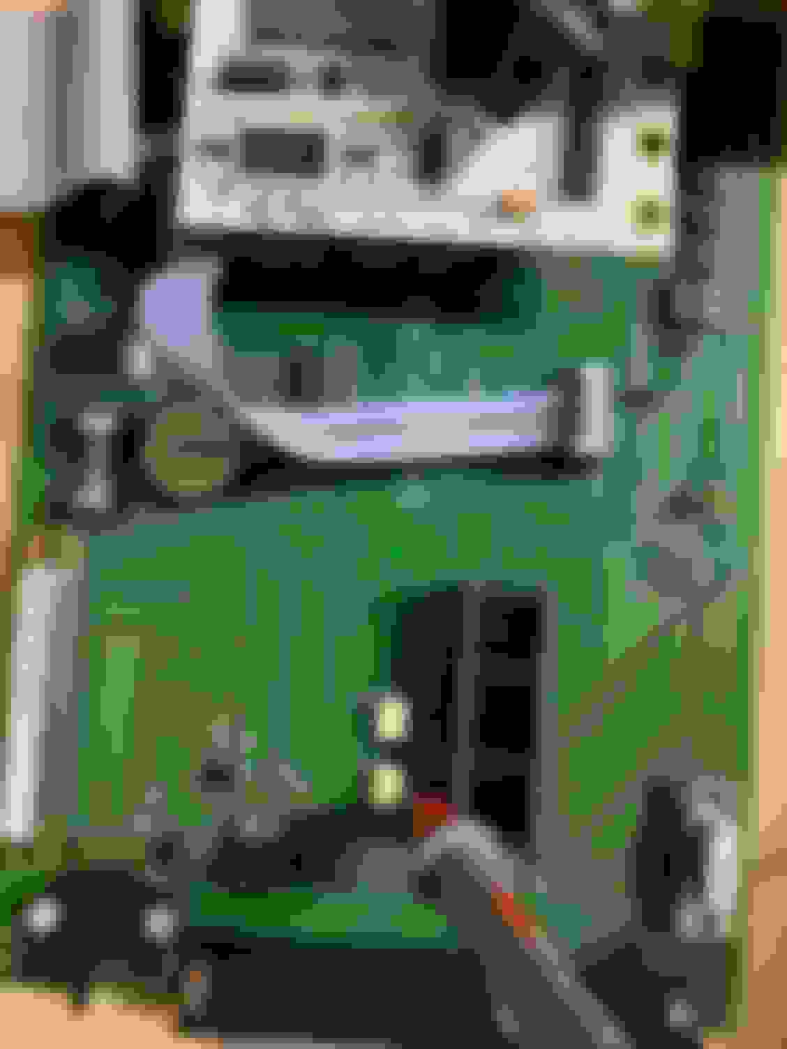
Does anyone recognize who makes this so I can perhaps get some help? It has no potentiometers to adjust and JP1 a J1 have no jumpers at all. J7 has a jumper but it’s hidden under another board right behind the map sensor.
That latest log still doesn't show a cam signal. Here's what it should look like. Green line is cam, blue crank, red is sync loss. You have a lot of red because there's no cam signal.
So I tried replacing the cam sensor entirely and when I took a composite log, it caused me to lose crank sensor reading as well. Swapped back to original cam sensor and crank signal came back but still no cam. I’ve send dimitri a message in hopes he can steer me in the right direction re: JP1 and J1. JP7 on my board has 3 pins. And two of them are jumpered. I’ve tested continuity on the power, ground and signal wires on both crank and cam, both are good. Can anyone tell me, in cranking settings, will rising edge or falling edge make a difference when it comes to getting the correct signal? Appreciate the replies
edit: I think it’s worth mentioning that the car runs fine on the oem ecu, with maf connected. the car is a 2000 Miata NB non vvt
This board runs optoisolators, there are no jumpers to set whatsoever. Either the optoisolator OK1 under the blue board is faulty or the input on the MS3 daughterboard is faulty.
This board runs optoisolators, there are no jumpers to set whatsoever. Either the optoisolator OK1 under the blue board is faulty or the input on the MS3 daughterboard is faulty.
I really appreciate the reply! Can you tell me, are either of those replaceable? If so, would you be willing to point them out? Or better yet, can I send it in for repair? I purchased this off ebay, guess I know why now
This board runs optoisolators, there are no jumpers to set whatsoever. Either the optoisolator OK1 under the blue board is faulty or the input on the MS3 daughterboard is faulty.
I’ve managed to locate the OK1 optoisolator, is anyone able to help me figure out a way I can check voltages or test it to make sure it’s still operational? Thanks
This board runs optoisolators, there are no jumpers to set whatsoever. Either the optoisolator OK1 under the blue board is faulty or the input on the MS3 daughterboard is faulty.
so I’ve done some research and traced the input pin from cam sensor to pin 2 of optoisolator ok1 and continuity checks out. I’ve also done basic resistance tests across anode (pin1) and cathode (pin2), I get a reading of .812m ohm with red lead on pin 1 (anode) and when switching leads I get infinite. also tested the emitter (pin 4) and collector (pin 5), I get 4.984k ohm reading with red lead on pin 5, 4.046k ohm with red lead on pin 4. Resistance seems to come in very close across the board between ok1 and ok2. Reverant, do you have any more thoughts on this? Thank you
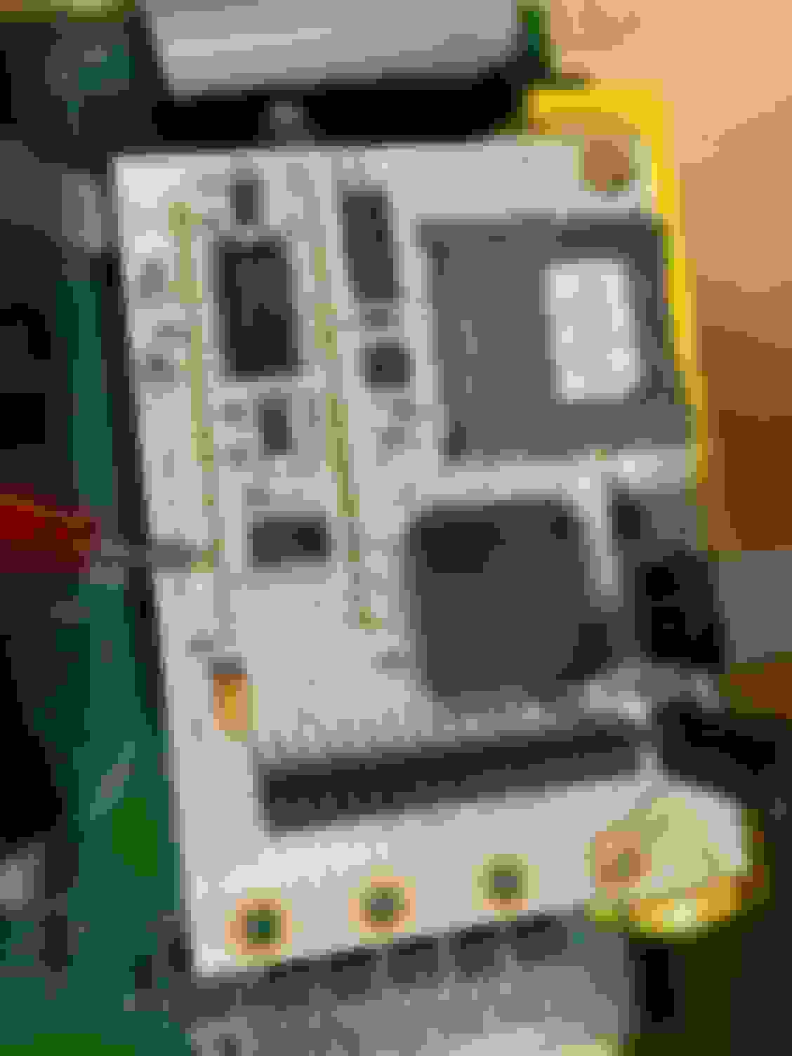
I am able to trace continuity from the collector pin 5 on ok1 to a pin as seen in picture on the ms3 daughterboard. From that pin, I can get continuity to the processor, also as seen. Does this mean that it’s possible the input on daughterboard is good?
Tap the pin of the daughterboard (the one you put the red probe on) to ground repeatedly and check if you get a cam signal on the composite logger. If you do, the daughterboard/processor is fine and you probably need to replace the optoisolator.
Tap the pin of the daughterboard (the one you put the red probe on) to ground repeatedly and check if you get a cam signal on the composite logger. If you do, the daughterboard/processor is fine and you probably need to replace the optoisolator.
well I went ahead and did this and still received no cam signal. Guess the daughter board it is. thank you for your help
Last check before you go on replacing it, go to File -> Vehicle Projects -> Project properties -> Settings -> PORT_STATUS: Activated.
Now create a new dashboard, you'll have the status of each processor pin (both in and out) as an indicator, PORTXn, on the bottom. Check for the PORTTn indicators, PORTT5 should be blinking when you tap the processor's cam input to ground.
portT5 does indeed change from green to white when I ground out the pin on daughterboard


 0
0