A better Spark Out circuit.


 03-26-2011, 08:03 AM
#123
Elite Member

iTrader: (10)
Join Date: Jun 2006
Location: Athens, Greece
Posts: 5,977
Total Cats: 356
I have an even better inverted output circuit, no transistors needed. You need:
2x 100Ohm resistors
2x 100KOhm resistors
2x clipped legs from diodes (a little thicker than resistor legs)
Do NOT install any of the components required for the LED circuits (D14, D15, D16, R24, R25, R26, R27, R28, R29, Q6, Q7, Q8)
Install the 100Ohm resistors in place of R26 and R29. Install the 100KOhm resistors like this: One leg of the resistor goes to the round hole of the LED (ie the bottom of the two holes) and the other leg of the resistor goes to the top hole of the three transistor holes. Then connect the bottom leg of the 100K resistor with the bottom leg of the 100Ohm resistor. Output to the coil is the hole of the R24, R28 resistor. Like this:
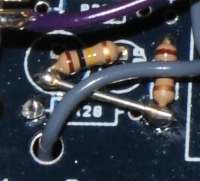
Win!
2x 100Ohm resistors
2x 100KOhm resistors
2x clipped legs from diodes (a little thicker than resistor legs)
Do NOT install any of the components required for the LED circuits (D14, D15, D16, R24, R25, R26, R27, R28, R29, Q6, Q7, Q8)
Install the 100Ohm resistors in place of R26 and R29. Install the 100KOhm resistors like this: One leg of the resistor goes to the round hole of the LED (ie the bottom of the two holes) and the other leg of the resistor goes to the top hole of the three transistor holes. Then connect the bottom leg of the 100K resistor with the bottom leg of the 100Ohm resistor. Output to the coil is the hole of the R24, R28 resistor. Like this:
Win!

Reply
 0
0

0
 03-27-2011, 07:50 AM
#125
Elite Member
iTrader: (10)
Join Date: Jun 2006
Location: Athens, Greece
Posts: 5,977
Total Cats: 356
The BC547 has the pins reversed compared to the 2N3904, so you should put it the other way around. It also can sink half the current, but I don't think that would be a problem. Why not do what I described above?
Reply
0
0
 08-22-2011, 06:56 PM
#129
Newb

Join Date: Jul 2008
Posts: 19
Total Cats: 0
Can I use Reverant's even better inverted output circuit alongside Braineak's fan mod on post #4 on the "how to" guide? (this one: https://www.miataturbo.net/useful-saved-posts-8/how-make-install-your-own-diy-megasquirt-13676/)
(this would require me to leave in D15, R25, R27 and swap out Q7 for Q4 - and hence conflicts with Reverant's instruction to leave out these components)?
(this would require me to leave in D15, R25, R27 and swap out Q7 for Q4 - and hence conflicts with Reverant's instruction to leave out these components)?
Reply
0
0
08-22-2011, 07:34 PM
#130
Boost Pope

Thread Starter
iTrader: (8)
Join Date: Sep 2005
Location: Chicago. (The less-murder part.)
Posts: 33,027
Total Cats: 6,593
I have an even better inverted output circuit, no transistors needed.
(...)
Install the 100Ohm resistors in place of R26 and R29. Install the 100KOhm resistors like this: One leg of the resistor goes to the round hole of the LED (ie the bottom of the two holes) and the other leg of the resistor goes to the top hole of the three transistor holes. Then connect the bottom leg of the 100K resistor with the bottom leg of the 100Ohm resistor. Output to the coil is the hole of the R24, R28 resistor. Like this:
So, I guess it would work, it just sort of bothers me to connect CPU pins directly to ignition coils, and to operate this closely to the published maximums.
Reply
0
0
08-23-2011, 02:01 AM
#131
Elite Member
iTrader: (10)
Join Date: Jun 2006
Location: Athens, Greece
Posts: 5,977
Total Cats: 356
Joe, that is how it is done on the microsquirt and microsquirt module. So I guess it is perfectly safe. I've been doing this for quite a while, no problems whatsoever.
Reply
0
0
01-20-2012, 01:26 PM
#132

I have d14 and d16 installed on my board, after doing this mod should they be on or off when I power up the ms2? They are always on right now....
When q6 has no signal at its base does that mean d16 is conduction to ground, so it's on?
I do have the spark output set to inverted in tuner studio. Not sure if the burn is working or not though.
I'm new at this so please be gentle.
When q6 has no signal at its base does that mean d16 is conduction to ground, so it's on?
I do have the spark output set to inverted in tuner studio. Not sure if the burn is working or not though.
I'm new at this so please be gentle.
Reply
0
0

 01-31-2012, 08:03 PM
#137
hang on, so are we saying that DIYPNP has the output inverted and therefore doesn't need to have the coils unplugged when burning - so why do DIYAutotune still recommend it in their online docs?
http://www.diyautotune.com/diypnp/ap...3-16b6-mt.html
http://www.diyautotune.com/diypnp/ap...3-16b6-mt.html
Reply
0
0
01-31-2012, 09:56 PM
#139
Boost Pope
Thread Starter
iTrader: (8)
Join Date: Sep 2005
Location: Chicago. (The less-murder part.)
Posts: 33,027
Total Cats: 6,593
The selection of "Normal" or "Inverted" in the software has no effect whatsoever on whether the spark outputs will float high when the MS is first powered on or during a reflash. That is purely a function of the design of the circuit which will drive the coils. The software selection is used to match the circuit design so that the system functions properly in normal operation (after the CPU has booted up and is operating.)
If you build an MS1 or MS2 per the "old" instructions, then you must select "Not Inverted" in the software. (This is ironic, and a poor choice of words, as that circuit is technically inverting relative to the CPU.)
If you build the system as per my "improved" spark output driver, then you must select "Inverted" in the software. (Which is, again, ironic, as my circuit is technically non-inverting.)
But again, the software setting is used only to make the behavior of the CPU match the design of the circuit while it is on-line and operating normally. What happens before the CPU is booted up (or while it is offline as during a reflash) is outside the software's control.
Originally Posted by gslender
hang on, so are we saying that DIYPNP has the output inverted and therefore doesn't need to have the coils unplugged when burning - so why do DIYAutotune still recommend it in their online docs?
Reply
0
0
02-01-2012, 09:30 AM
#140
Boost Czar

iTrader: (62)
Join Date: May 2005
Location: Chantilly, VA
Posts: 79,494
Total Cats: 4,080
Joe, this is the DIYPNP (micosquirt module) spark outputs:
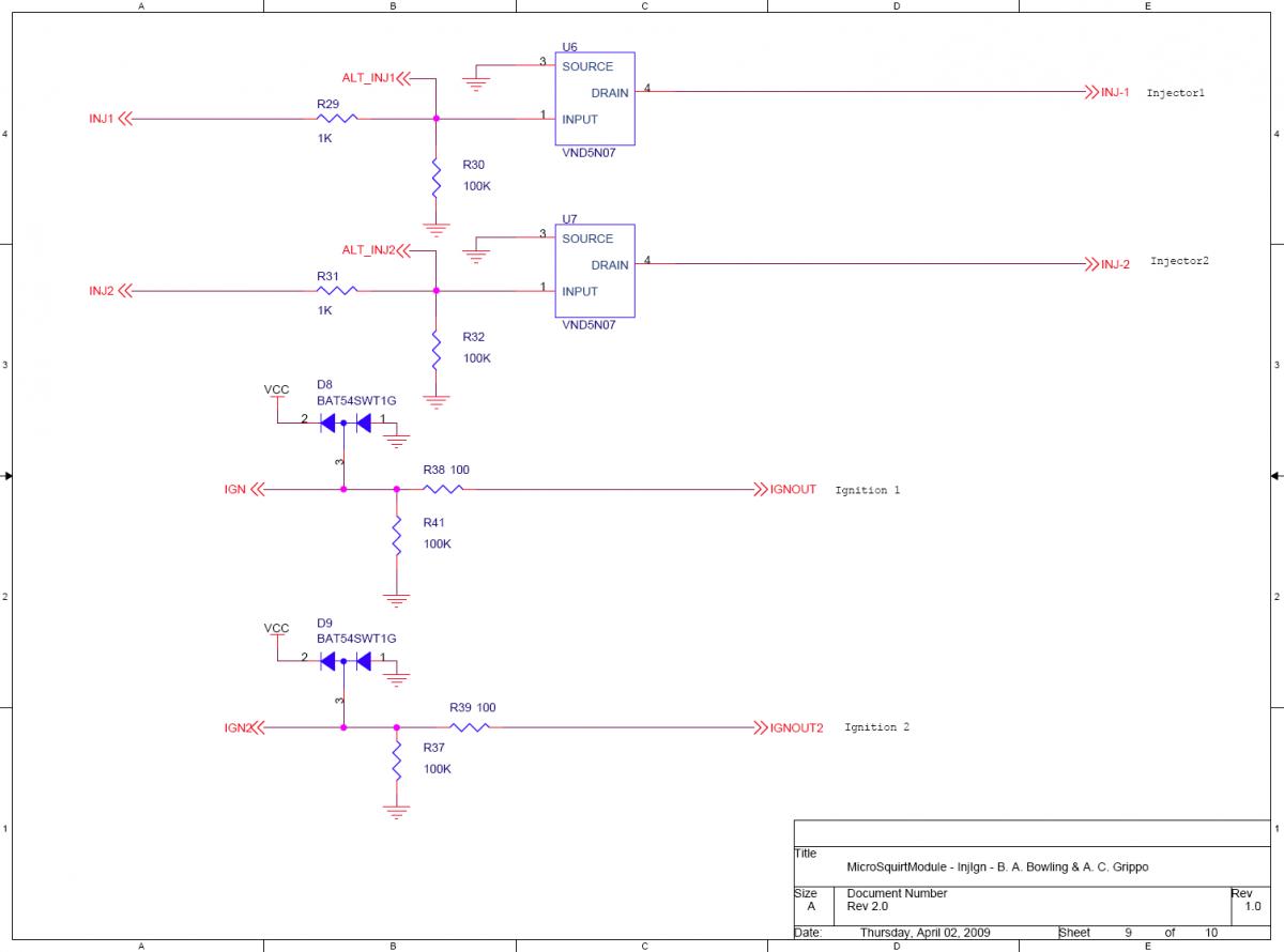
It's kinda like coming off R29 and R26 directly and running inverted. I think I had my MS setup this way when I first installed it in 2006.
It's kinda like coming off R29 and R26 directly and running inverted. I think I had my MS setup this way when I first installed it in 2006.
Reply
0
0


