When you click on links to various merchants on this site and make a purchase, this can result in this site earning a commission. Affiliate programs and affiliations include, but are not limited to, the eBay Partner Network.
No progress with the 10k pull up, at least I can run it in 2 now. Must be the ******* switch. I looked into it and I see the thick ground but it all looks properly connected but could not take out that part without having to disconnect all the cables that go to the heater box. I'm open for ideas.
I haven't fixed this **** yet. Summer coming up and I think about it again.
Would it help to use a relay before the input to the MS? The ground from the switch closes a relay that goes to the best ground in the county and that triggers the MS?
Can I do this electonically in the protoboard with a transistor or something like that?
Does your idle also drop randomly and almost kills the engine? I have a weird issue where my closed loop targets 800rpm instead of the 900 of the AC-ON, but the clutch is still engaged. So I had to set the AC min RPM to something like 750 or it would just take the engine with it.
Well I might be going skookum about this but I got an arduino nano that I'll use to filter the input to the MS.
I'm gonna get the input from the pullup circuit that would go to my JS11, intercept it with the analog in of the arduino, then code it so it's this board the one giving the HIGH in to the JS11, and not the protoboard.
When the AC is off the value at the pullup is 5v no problem, but it only drops to 2v in speed 4 of the fan. A problem for the MS, but not an issue for the resolution of the arduino. I have 5v/1024 values, so 2v would be around 512, so I'll set it so if the value is under 800 adc, sends a HIGH to the output that goes to JS11, and when it goes over 900 then goes to LOW (some hysteresis in case one day the ground is slightly worse or something, I'm sure that with AC off it's gonna be well above 900 anyway)
I'll report back soon. I'm already getting other ideas to use this thing for. Canbus with other analog inputs, temps and what not, should work. The board was 4 bucks, so even if it's overkill, can't beat the cost of having working AC (assuming this works).
Plenty of room in my MS2 DIY box, so I can play with this ****, but I don't see why you couldn't just hotglue this tiny board to the outside of an PNP or the inside of the box and wire it to it. I can power it from the 5v from the proto, this thing, uses like 20mA of current
Buy an Arduino nano without headers (the pins sticking out).
Get some 22awg single strand wire and connect:
Arduino / MS
-D8 -> JS11 (or whichever input you are using.)
-A2 -> input from the AC switch, still use the pull-up circuit.
-GND -> Proto GND
-5v PIN -> Proto 5V.
If you choose another pin for whatever reason, change the declarations in the code below.
Code here:
int acIn = A2; // PIN A2 as the input from the AC switch
int acOut = 8; // Digital Pin 8 as the pin for the High/Low output
int analIn = 0; // (pun intended) variable to store the value coming from the AC in reading
int i = 0 ; // for the loop I use for average values
int sum = 0 ; //sum for the average
void setup() {
Serial.begin(9600); //only used for debugging, not really needed.
pinMode(acOut, OUTPUT); //set the acOut pin (D8) as an output.
}
void loop() {
// read the value from the AC swtich 10 times and average it.
sum=0;
for (i=0; i<10; i++){
analIn = analogRead(A2);
sum = sum + analIn;
delay(10);
}
analIn = sum / 10; //store the average value of 10 readings
// 0v = 0, 5v = 1023, in speed 4, my voltage readings are around 2v, 5v when AC OFF
if (analIn < 650){ //if the readings are lower than ~3.17v then set it High
digitalWrite(acOut, HIGH);
} else if(analIn > 850){ //I use a high value because I for sure have 5v when AC is off, I don't want it jumping off
digitalWrite(acOut, LOW);
}
Serial.println(analIn); //just printing the read values for debugging, I used it to figure out what values I needed
}
That's it, over the top, but it gets the **** done, I was tired of dealing with that AC bullshit, I consider my ECU conversion finally over, that was the last bit I needed. After this, my car is 100% more drivable in summer months, couldn't be happier.
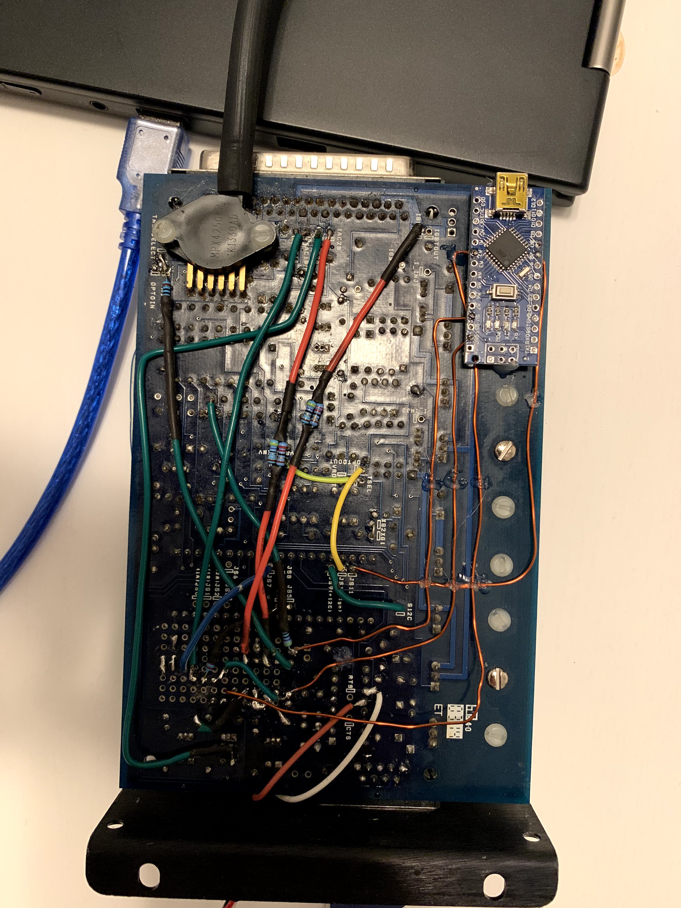
Don't laugh at my wires, but this is what it looks like. Progress over perfection. You can even drill a hole on the sideplate to access the USB.
Also I've considering adding a diode on the 5v line so your Arduino never tries to power the ECU when you connect the USB. But the 0.6v drop concerns me. Through the 5v pin you should only feed 5v, if you're planning on using 12v, use VIN. I don't see myself connecting the USB anytime soon if this works fine, so I got lazy and left it like that. But if I add CAN and a few things to this thing I would probably do something then.
Last edited by Nicolas L; May 20, 2020 at 11:59 PM.
For anyone else having issues with ac compressor cycling off at certain fan levels :
It's either your blower motor resistor block, corrosion on some connector pins or the fan level / ac switch inside the vacuum control panel itself. There's a copper disc with glide contacts and ancient dried up dielectric grease inside the switch.
I've only ever had issues on fan level 3 / medium-high.
.) swapped resistor block and cleaned up the oxidized connector pin on it. Specifically the pin for medium-high was quite greenish looking. Still happened, maybe less often.
This is how the pin inside the connector was looking, top already having been sanded down.
.) replaced the fan control / ac switch assembly inside my hvac control panel with one from a spare I had with broken frame. Also opened it up and cleaned and lightly sanded the copper disc and glide contacts at the front and back portion of it. Thin layer off fresh dielectric grease on everything.
It's fixed now. Ac running permanently on fan level 3, no cycling.
I guess it's a compounding issue where voltage levels behind the blower motor resistor block drop below a certain level due to increased resistance from old switches and connectors ?
Idk


 0
0