
DIYPNP: PE1 flyback issue?


Thread Starter
Junior Member
Joined: Jun 2007
Posts: 411
Total Cats: 0
Hi guys,
I didn't want to clutter the nice closed loop idle discussion in the other thread, so I made a new one for this issue.
I ran a wire from PE1 to 1J, so I could use the AC trigger signal to also trigger spark table switching. Worked fine, until I noticed these symptoms:
Car warm, turn off AC blower, with AC compressor button still pushed in/ON:
The AC clutch engages and the spark table switching engages.
If I push the AC compressor button to turn it off, the symptoms disappear. When both the blower switch and AC switch are on, there are no issues.
Is this flyback to the 1J wire? If so, why does it stop with the AC compressor switch, and not stop with the blower switch off?
Could it be a bad AC switch?
Could the source of the ground be PE1 itself? I double checked the wires/soldering, no issues with excess solder or bad insulation.
Thanks! XD
Reply
 0
0

0

Junior Member
Joined: Mar 2011
Posts: 163
Total Cats: 0
From: Guildford, UK
AC, I think works with a 2 switch to on. Button in AND fan on to work.
You'll need to set it up only to switch tables when both are on, no idea what to wire it to as I'm a

Interested to find out as I would like to do the same.
What happens when you turn off the AC button but leave the fan on???
You'll need to set it up only to switch tables when both are on, no idea what to wire it to as I'm a
Interested to find out as I would like to do the same.
What happens when you turn off the AC button but leave the fan on???
Reply
0
0


Thread Starter
Junior Member
Joined: Jun 2007
Posts: 411
Total Cats: 0

Well I did ask you before I did it, I assumed silence was consent

Wait wait. Relay 1 is taken by the AC fan. Here's a (blurry) pic:
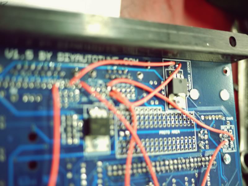
So it's PE1-->relay 2 IN-->relay 2 OUT---> 1J
Reply
0
0

Ah yes. You have 1Q going into relay, and 1J out to activate the A/C. IJ should be bale to go into PE1 just fine and be protected with the diode from that relay, but it could be overloading it.
Try running 1J to, input 2 IN, OUT to PE1, see if it clears up.
Try running 1J to, input 2 IN, OUT to PE1, see if it clears up.
Reply
0
0
Thread Starter
Junior Member
Joined: Jun 2007
Posts: 411
Total Cats: 0
Houston, we have a problem...
What's the difference between 'input' and 'relay'? Cos as it is, 1Q-->input 1 IN-->input 1 OUT-->1J. Do I need to move THOSE to a relay?
Input 2 is used by the launch control circuit.

Greg
What's the difference between 'input' and 'relay'? Cos as it is, 1Q-->input 1 IN-->input 1 OUT-->1J. Do I need to move THOSE to a relay?
Input 2 is used by the launch control circuit.
Greg
Reply
0
0
Thread Starter
Junior Member
Joined: Jun 2007
Posts: 411
Total Cats: 0
For which?
1J-->RELAY 2 IN--->RELAY 2 OUT--->PE1?
The 1Q-->Input 1 IN-->Input 1 OUT-->1J is OK? No need to move it?
Which brings me back to--what's the difference between 'input' and 'relay'?
Sorry, need to be specific, I don't wanna open it up a third time
1J-->RELAY 2 IN--->RELAY 2 OUT--->PE1?
The 1Q-->Input 1 IN-->Input 1 OUT-->1J is OK? No need to move it?
Which brings me back to--what's the difference between 'input' and 'relay'?
Sorry, need to be specific, I don't wanna open it up a third time
Reply
0
0
Thread Starter
Junior Member
Joined: Jun 2007
Posts: 411
Total Cats: 0
From the CR thread, reposted here for completeness/ future reference...
When you say flyback spikes, that's flyback from 1J to PE1? Not something from PE1 to 1J?
Input 1 is used by the AC, Input 2 by launch control. Can I use relay 2 instead? Like this: 1J-->RELAY 2 IN-->RELAY2 OUT-->PE1?
So I have to give up launch control then?
Input 1 is used by the AC, Input 2 by launch control. Can I use relay 2 instead? Like this: 1J-->RELAY 2 IN-->RELAY2 OUT-->PE1?
Reply
0
0
Thread Starter
Junior Member
Joined: Jun 2007
Posts: 411
Total Cats: 0
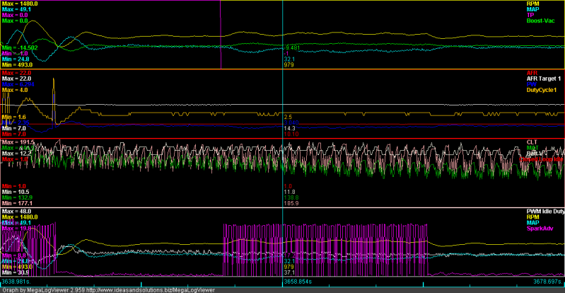
I thought I had this issue resolved already. I routed the trigger from 1J through Input 2 to eliminate the flyback. But it's back!
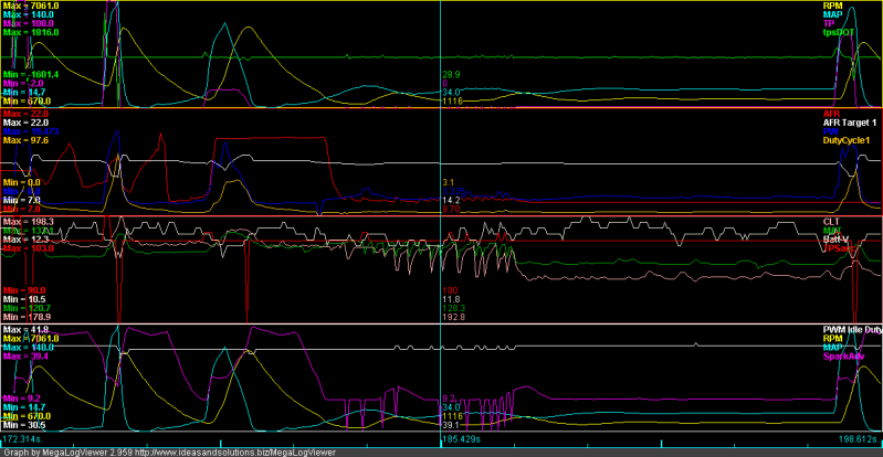
I notice when this happens I have an issue with the compressor not turning on when engine is hot. I assumed it was an issue with the AC compressor clutch, but the clutch has been replaced. Since flyback from 1J is already a non issue, I'm now looking at a cause upstream, affecting the 1Q (input from AC switch). The only things on that circuit are the AC switch and the thermoswitch. Could I have a bad switch (the button part controlling the compressor)?
The issue is worse now because I have a working TPS-- so AE is being triggered at idle!
Reply
0
0

Thread
Thread Starter
Forum
Replies
Last Post
bigmackloud
Miata parts for sale/trade
19
Jan 8, 2021 11:24 AM


