
Brain built MS, Added VTPs, No Signal in TS


Thread Starter
Elite Member
Joined: Apr 2010
Posts: 2,826
Total Cats: 66
From: Newcastle, Australia
Hey guys,
I have a brain built ms2, Just added a variable TPS, it works fine, no breaks in the circuit leading back to the factory plug, but I cannot get any signal at all in TS, and even when trying to calibrate TPS I just get 0 and 0.
Any Suggestions?
Dann
I have a brain built ms2, Just added a variable TPS, it works fine, no breaks in the circuit leading back to the factory plug, but I cannot get any signal at all in TS, and even when trying to calibrate TPS I just get 0 and 0.
Any Suggestions?
Dann
Reply
 0
0

0

Check what ya getting at the harness (remove ECU) and you should have variable resistence from open throttle to closed throttle. Also, are you sure the Brain built ECU has been wired for VTPS - as if he wired it for stock he might/should have put in a resistor to ensure that stock TPS doesn't kill the 5V rail and this would mean the VTPS would be zero/zero.
In fact, if the ecu is powered, the TP in TS should float if the ECU is wired to work with a VTPS. If it sits steady on zero then it is probably (very likely) wired for stock TPS and has the resistors in place etc.
G
In fact, if the ecu is powered, the TP in TS should float if the ECU is wired to work with a VTPS. If it sits steady on zero then it is probably (very likely) wired for stock TPS and has the resistors in place etc.
G
Reply
0
0


Joined: Sep 2005
Posts: 34,428
Total Cats: 7,548
From: Chicago. (The less-murder part.)
Since you're noting that you have added a VTPS, I assume you have a '90-'93 car.
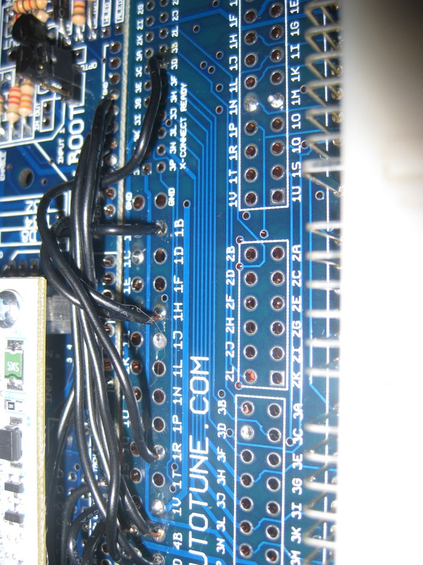
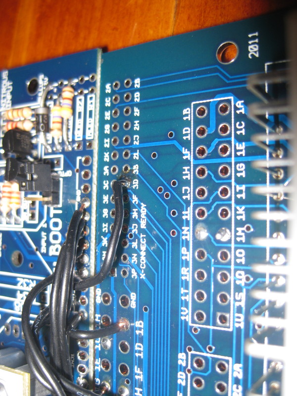
In order for the TPS to function, you need two wires running between it and the MS. One is the TPS signal itself, from pin 22 of the MS to the wiper terminal of the TPS.
The other is the +5 supply which the TPS needs to operate. This goes from pin 26 of the MS to the side of the TPS which is opposite ground.
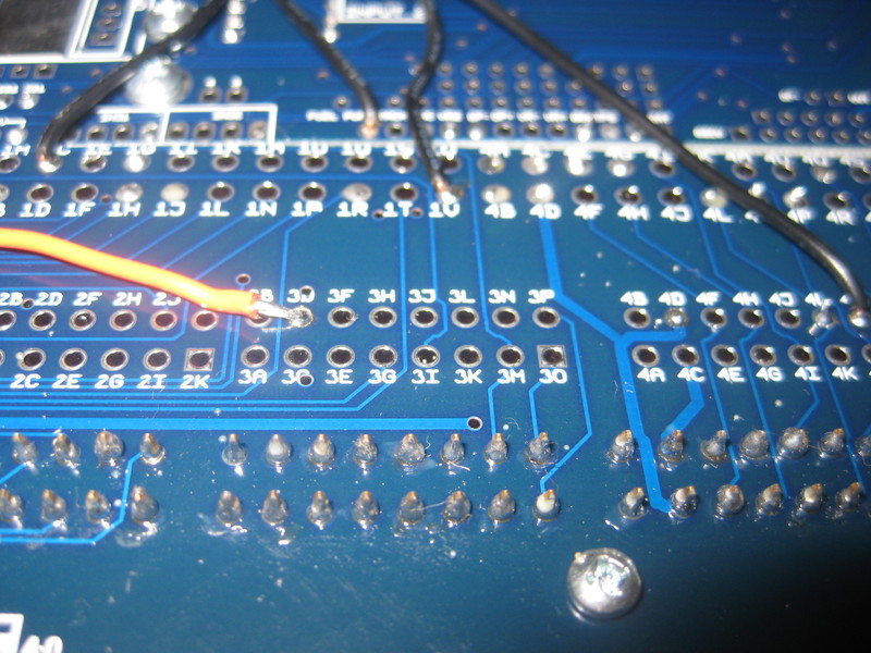
There is no absolute standard for how this is done in a 1.6 MT car, however one wire will go to position 1N of the ECU harness (a red wire) and the other to position 2L (a light green / red wire). If these two wires are reversed (and again, their position is relative to how the TPS itself is wired on the other end) there is some risk of damage to the TPS.
So, details man! What's wired where?
In order for the TPS to function, you need two wires running between it and the MS. One is the TPS signal itself, from pin 22 of the MS to the wiper terminal of the TPS.
The other is the +5 supply which the TPS needs to operate. This goes from pin 26 of the MS to the side of the TPS which is opposite ground.
There is no absolute standard for how this is done in a 1.6 MT car, however one wire will go to position 1N of the ECU harness (a red wire) and the other to position 2L (a light green / red wire). If these two wires are reversed (and again, their position is relative to how the TPS itself is wired on the other end) there is some risk of damage to the TPS.
So, details man! What's wired where?
Reply
0
0
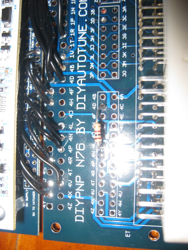
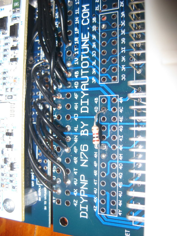
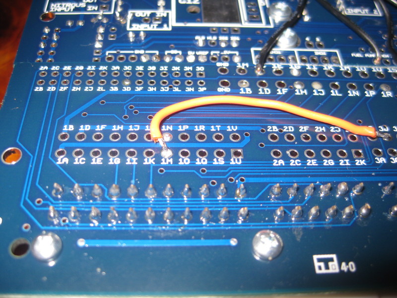

Correct. Or just remove your orange wire, and move the black on 3D to 1N. That was the intent of putting the wire there.
Then cut off the resistor. That's holding the signal to ground, otherwise it floats and your TPS constantly increases over time while driving.
You'll wire your vTPS so that the:
5vref wire goes to the RED wire of the tps harness.
Ground goes to the BLK/GREEN wire of the tps harness.
TPS Sig goes to the GREEN/RED wire of the tps harness.
Reply
0
0
Thread Starter
Elite Member
Joined: Apr 2010
Posts: 2,826
Total Cats: 66
From: Newcastle, Australia
Ok so a few days on and still I cannot get a TPS signal.
I have a working TPS wired DIRECTLY to the board and I still get a count of 0 and 0.
Any suggestions?
I have the wiper wire to SG, and the other 2 are to TPS and VREF.
The resistor has been removed.
Dann
I have a working TPS wired DIRECTLY to the board and I still get a count of 0 and 0.
Any suggestions?
I have the wiper wire to SG, and the other 2 are to TPS and VREF.
The resistor has been removed.
Dann
Last edited by nitrodann; Feb 6, 2012 at 01:14 AM.
Reply
0
0
Did you verify your wiring in the engine harness?
it should be this:
When I read this
It makes me think you wired the TPS signal to ground, thus why it's sitting pretty at 0%. The TPS input is floating, if it's not grounded it will constantly increase in voltage and everytime you click get current it will increase 1 point ever second or so.
What TPS is this exactly?
it should be this:
You'll wire your vTPS so that the:
5vref wire goes to the RED wire of the tps harness.
Ground goes to the BLK/GREEN wire of the tps harness.
TPS Sig goes to the GREEN/RED wire of the tps harness.
5vref wire goes to the RED wire of the tps harness.
Ground goes to the BLK/GREEN wire of the tps harness.
TPS Sig goes to the GREEN/RED wire of the tps harness.
When I read this
I have the wiper wire to SG
What TPS is this exactly?
Reply
0
0
Thread Starter
Elite Member
Joined: Apr 2010
Posts: 2,826
Total Cats: 66
From: Newcastle, Australia
Its a TPS from a automatic RB30E, VL commodore.
It works just fine.
I have never ever seen any values other than 0 and 0 when checking TPS, this includes when It had a stock TPS, and with the stock TPS disconnected, and before I modified anything on the board from what you gave it to me as.
What could cause this?
Dann
It works just fine.
I have never ever seen any values other than 0 and 0 when checking TPS, this includes when It had a stock TPS, and with the stock TPS disconnected, and before I modified anything on the board from what you gave it to me as.
What could cause this?
Dann
Reply
0
0
Thread Starter
Elite Member
Joined: Apr 2010
Posts: 2,826
Total Cats: 66
From: Newcastle, Australia
Also, yes I verified the engine harness, all of my board wiring matches the cars wiring that works.
I mean, I soldered the TPS directly to the board. straight to it with a foot of wires.
Dann
I mean, I soldered the TPS directly to the board. straight to it with a foot of wires.
Dann
Reply
0
0

Thread
Thread Starter
Forum
Replies
Last Post
bigmackloud
Miata parts for sale/trade
19
Jan 8, 2021 11:24 AM
Zaphod
MEGAsquirt
47
Oct 26, 2018 11:00 PM
StratoBlue1109
Miata parts for sale/trade
21
Sep 30, 2018 01:09 PM


