
CANBUS question

Thread Starter
Elite Member
iTrader: (16)
Joined: Aug 2007
Posts: 9,406
Total Cats: 559
From: Houston, TX
I got a question about canbus on the MS3 PRO. I've never used it before.
My question is, can I setup the MS3 PRO to send messages based on conditions?
For example, if coolant temp above 195*F, send a certain command, if below 190*F, send a different command.
That way another can device could receive those messages and act accordingly.
My question is, can I setup the MS3 PRO to send messages based on conditions?
For example, if coolant temp above 195*F, send a certain command, if below 190*F, send a different command.
That way another can device could receive those messages and act accordingly.
Reply
 0
0

0
All-round "Good Guy"

Joined: Dec 2009
Posts: 1,036
Total Cats: 266
From: Brisbane, AUSTRALIA
I haven't looked at it recently but the last time I configured my broadcasted CAN messages, they could only be sent at a periodic rate of my choice.
Your "other device" should be listening for the CAN messages and act accordingly based on the values.
Your "other device" should be listening for the CAN messages and act accordingly based on the values.
Reply
0
0

I'm not sure what you'd need to have the megasquirt do that for, OEM hardware integration?
Whatever device you use to read the proposed commands would be able to poll the coolant temp at a reasonable rate and react off that accordingly. You might need to program hysterics on top of that, or whatever else you'd need. You could also just listen to the global dashboard broadcast, no polling needed.
MS3 has canbus passthru, and tunerstudio will let you make a new "ecu." If you program the device in advance, you can program it "live" through tunerstudio just like the megasquirt, which is basically sending commands to change memory in the remote device. So in your case you could change the temp set points, or a 2d table with a duty cycle lookup, or whatever else you'd like really. Your programming on the device just needs to use that dedicated memory as variables.
Or you could skip all that and just program the device another way, quick and dirty.
That's more or less how most everything "megasquirt can" works.
Reply
0
0
Elite Member
Joined: Mar 2007
Posts: 5,306
Total Cats: 885
From: Santa Clara, CA
One option is to build an Arduino to sit in the middle and do the translation. Have it listen to the CAN bus broadcasts from the megasquirt and implement the trigger logic that you care about, then generate another CAN bus message to trigger whatever the other device is. $20 in hardware and 100 lines of C.
--Ian
--Ian
Reply
1
1

Junior Member
Joined: Jun 2015
Posts: 182
Total Cats: 58
From: VIC, Australia
It is possible to set something up although may be a bit limited depending on what you want to do.
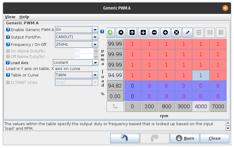
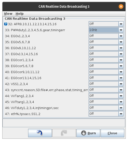
You could use one of the generic PWM outputs, set it to output on a CAN port and then receive the signal through the data broadcasting message no.33.
The port status can also be transmitted on message no.51 which might be useful.
Using your example of coolant...
Setup PWM output with 1 as active state and 0 as inactive
Then set base message ID, in this case 1520 in dec or 0x5F0 in hex.
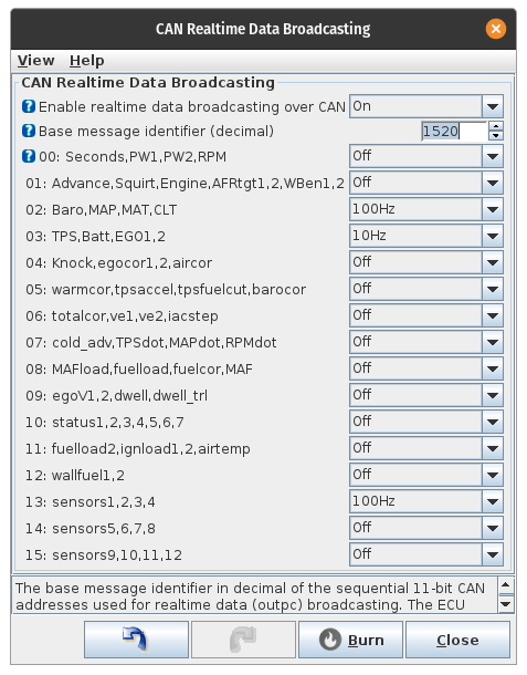
Then turn on message 33 which will be 1520+33. So message ID will be 1553 dec or 0x611 hex.
Haven't tried this so no idea if it'll work or if it's what you are looking for...
You'd also need to be able to configure the receiving device to interpret the information correctly.
You could use one of the generic PWM outputs, set it to output on a CAN port and then receive the signal through the data broadcasting message no.33.
The port status can also be transmitted on message no.51 which might be useful.
Using your example of coolant...
Setup PWM output with 1 as active state and 0 as inactive
Then set base message ID, in this case 1520 in dec or 0x5F0 in hex.
Then turn on message 33 which will be 1520+33. So message ID will be 1553 dec or 0x611 hex.
Haven't tried this so no idea if it'll work or if it's what you are looking for...
You'd also need to be able to configure the receiving device to interpret the information correctly.
Reply
0
0
Thread Starter
Elite Member
iTrader: (16)
Joined: Aug 2007
Posts: 9,406
Total Cats: 559
From: Houston, TX
OK new question regarding CANBUS.
I know there is a way to add analog inputs via CANBUS to the MS3 PRO. I can put together an arduino/CANBUS module so I can make the arduino send data over CANBUS to the MS3 PRO
But the question is, how do I setup the MS3PRO to receive this data? I keep googling and I read in one post someone says the MS3PRO has to request something, and then you send it the values for the variables it's expecting. Lokiel mentioned something like this, but how do I actually do it?
Trying to find a way to add some extra analog inputs and not spend 1500 on a new MS3 with a few more analog input wires.
Reply
0
0
Elite Member
Joined: Mar 2007
Posts: 5,306
Total Cats: 885
From: Santa Clara, CA
OK new question regarding CANBUS.
I know there is a way to add analog inputs via CANBUS to the MS3 PRO. I can put together an arduino/CANBUS module so I can make the arduino send data over CANBUS to the MS3 PRO
But the question is, how do I setup the MS3PRO to receive this data? I keep googling and I read in one post someone says the MS3PRO has to request something, and then you send it the values for the variables it's expecting. Lokiel mentioned something like this, but how do I actually do it?
Trying to find a way to add some extra analog inputs and not spend 1500 on a new MS3 with a few more analog input wires.
I know there is a way to add analog inputs via CANBUS to the MS3 PRO. I can put together an arduino/CANBUS module so I can make the arduino send data over CANBUS to the MS3 PRO
But the question is, how do I setup the MS3PRO to receive this data? I keep googling and I read in one post someone says the MS3PRO has to request something, and then you send it the values for the variables it's expecting. Lokiel mentioned something like this, but how do I actually do it?
Trying to find a way to add some extra analog inputs and not spend 1500 on a new MS3 with a few more analog input wires.
--Ian
Reply
1
1
All-round "Good Guy"
Joined: Dec 2009
Posts: 1,036
Total Cats: 266
From: Brisbane, AUSTRALIA
OK new question regarding CANBUS.
I know there is a way to add analog inputs via CANBUS to the MS3 PRO. I can put together an arduino/CANBUS module so I can make the arduino send data over CANBUS to the MS3 PRO
But the question is, how do I setup the MS3PRO to receive this data? I keep googling and I read in one post someone says the MS3PRO has to request something, and then you send it the values for the variables it's expecting. Lokiel mentioned something like this, but how do I actually do it?
Trying to find a way to add some extra analog inputs and not spend 1500 on a new MS3 with a few more analog input wires.
I know there is a way to add analog inputs via CANBUS to the MS3 PRO. I can put together an arduino/CANBUS module so I can make the arduino send data over CANBUS to the MS3 PRO
But the question is, how do I setup the MS3PRO to receive this data? I keep googling and I read in one post someone says the MS3PRO has to request something, and then you send it the values for the variables it's expecting. Lokiel mentioned something like this, but how do I actually do it?
Trying to find a way to add some extra analog inputs and not spend 1500 on a new MS3 with a few more analog input wires.
My sensor box "project" uses a Teensy 3.2, CAN transceiver, Pololu 36->5V daughter-board (hate external hardware converters), MAX232 chip (for Innovate Serial WBO2 and GPS Serial input - hate external hardware converters), accelerometer daughter-board, 2x128x64 OLED displays (these replace the 2x NB outer gauges), 3 digital inputs (1 to cycle through the OLED gauge displays which are configurable), 2x pressure sensors and 4x temperature sensors.
Apart from the GPS and OLED sensors, this all fits into an aluminium case the size of a matchbox to allow me to fit it anywhere.
The fuel gauge is also wired up since I've replaced the fuel sensor with an OLED gauge (having 2x OLED gauges allows me to display up to 8 values simultaneously and "balances" the look of the instrument cluster - each page can be configured to display 1, 2, 3 or 4 gauge values).
My custom-board also scales the 5V Temperature and Pressure sensor outputs down to 3.3V (using resistors in voltage divider circuits) because the Teensy clips them to 3.3V so you lose the upper range.
Scaling the signal prior to the Teensy means that you get a 3.3V 10-bit digital value close enough to what the original 5V 10-bit digital value is.
Since my sensor box communicates via CAN to the MS3, I can also display any MS3 value on the 2x OLEDs, not just those my sensor box project is handling and sending to the MS3.
I think that the Arduino Uno accepts 5V analogue inputs without clipping so you wont need to scale the sensors outputs (if the Arduino documentation says it's 5V tolerant, this actually means that it will handle 5V but will actually clip input to 3.3V).
I started with an Uno but my project quickly got out of hand and I ran out of memory on it - for extra temperature and pressure sensors it would be ideal though.
The pressure sensors wont need a pull-up resistor.
The temperature sensors will need a pull-up resistor - I used 2K49 resistors in conjunction with GM temperatures sensors since the MS3 already had the temperature profiles for these.
OK, that's the hardware, now for the software-side.
CAN is best handled in broadcast mode, just broadcast the data you want from your Arduino and configure the MS to listen for it - the request/response model is a pain in the **** and Tuner Studio isn't set up for it anyway - it IS setup for broadcast mode though!
Essentially CAN data consists of an address (treat this as a message type) and up to 8 bytes of payload data.
Assuming you want extra temperature and pressure sensors:
Define your CAN messages by assigning them a unique CAN address and what the payload contains (eg. T1+T2+T3+T4 or T1+P1+T2+P2 or P1+P2)
Your temperature and pressure values are 10-bit values so you'll need 2 bytes for each.
The following example defines a CAN Message with 2x Temperature values and 2x Pressure values in Message ID 821 in TunerStudio and how to transform the payload data:
1. Select CANbus/TestModes->CANReceiving
2. Set the first 4 Local value/channels to: ADC01, ADC02, ADC03, ADC04
3. Set the corresponding Std/Ext values to "Std"
4. Set the corresponding Identifier(desc) to "821"
5. Set the first 4 offsets to: 0, 2, 4, 6 (the temperature and pressure values take up 2x bytes each and there is a maximum of 8 bytes in a CAN payload)
6. Set the corresponding Size values to "B2U" (Binary Unsigned)
7. Set the corresponding Multiply to "1" (no multiplication factor needed)
8. Set the corresponding Divide values to "1" (no division factor needed)
9. Set the corresponding Add values to "0" (no addition factor needed)
10. Set Enable receiving CAN data to "ON"
11. Set Enable sharing CAN data to "OFF"
The following example shows how to map the transformed CAN payload into MS sensor data:
1. Select AdvancedEngine->GenericSensorInputs
2. Define each sensor by selecting the Sensor-Source (eg, CAN ADC01..CAN ADC04), entering a Field Name (eg. Oil Temp or Oil Pressure), Transformation (use Linear for Pressure, GM calibration for temperature), and Lag Factor (50 or 100 is typical here)
For Linear transformations, which are typically used by pressure sensors, define the 0V value and 5V values defined by the pressure sensor's documentation (some will only show the 0.5V and 4.5V values so you'll have to use your linear algebra skills to calculate the 0 and 5V values). If you have scaled the sensor's output from 5V to 3.3V, you must still use the 5V table value since the 10-bit digital value is still representing the full range of the sensor's output.
Apologies if I've missed something.
Reply
2
2

Thread
Thread Starter
Forum
Replies
Last Post


