
DIY MegaSquirt-II Wont Power up HELP!!!


Thread Starter
Newb
Joined: Nov 2016
Posts: 6
Total Cats: -4
Hello,
I would first like to say i think i may have messed up and any help or thoughts are welcome!
Items:
- MegaSquirt-II Programmable EFI System PCB3.0 � Kit
- DIYBOB Breakout Adapter � Nippon Denso 76 pin
- 24″ MegaSquirt Pigtail Harness
- 91 1.6L na miata
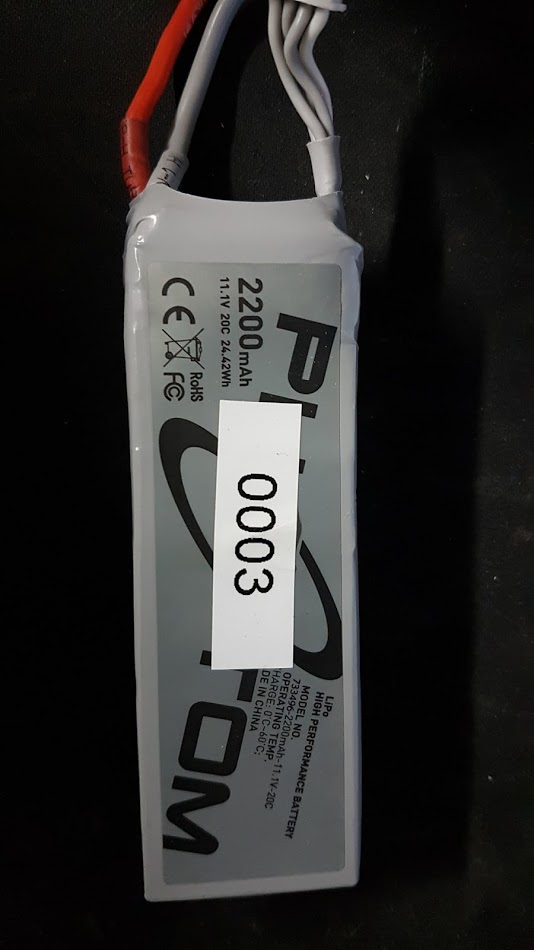
- 11.1 V 20c 24.42wh 2200mah battery
* all items were bought from DIYautotune
i am pretty confident in my soldering skils and i am not able to find any problem in a soldering issue.
i followed these instructions
Assembly Guide - MegaSquirt(R) V3.0 Main Board
on step 50. i followed the Hall/Optical/ect. path thinking that is what the 1.6 miata uses for tack (first thing im probably wrong at)
Step 69. i did not do this step because i didnt think it applied (probably wrong again!)
Step 71. current limit circuit for driver FET protection (i did this) seamed legit!
at this point i was done soldering the kit so i decided to fire it up on the desk to see if i could use it was tuner studio.
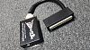
I applied power (11.1V) to pin 28 on the DB37 plug using the pigtail (red wire that said power)
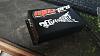
and for ground i used about 3-4 of the ground wires (assuming there all connected) and 3- 4 was all i could fit in my battery.
pic of the battery i used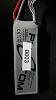
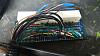
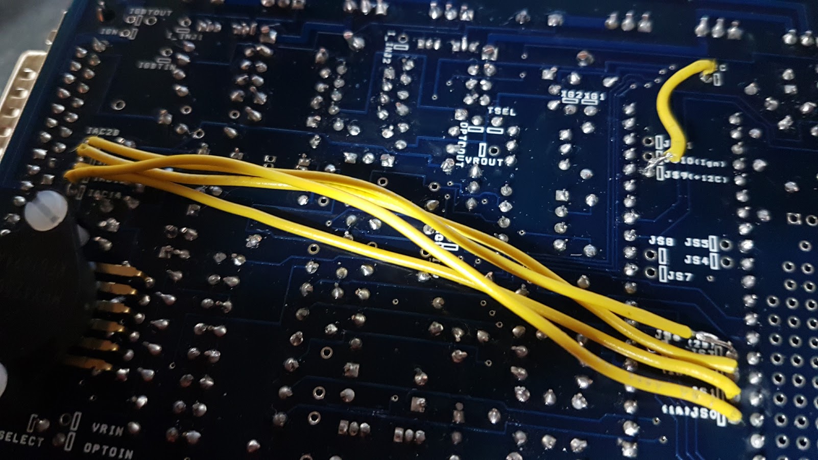
when i applied power for the fist time smoke came from the right side of the board.
picture from where the smoke came from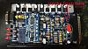
i thought the MOV1 blew so i replaced the Metal Oxide Varistor (MOV1) and i havent been able to get it to power on ever ever scene.
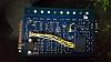
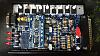
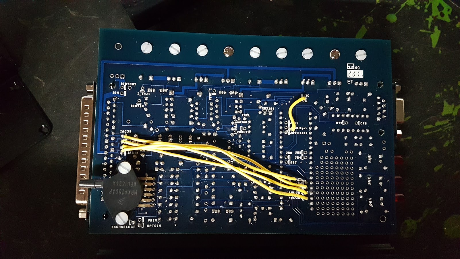
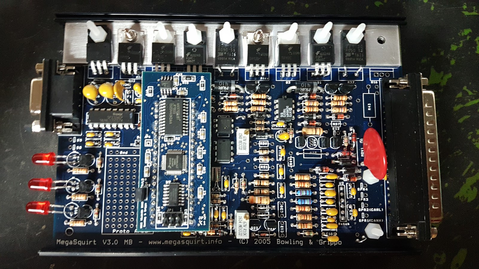
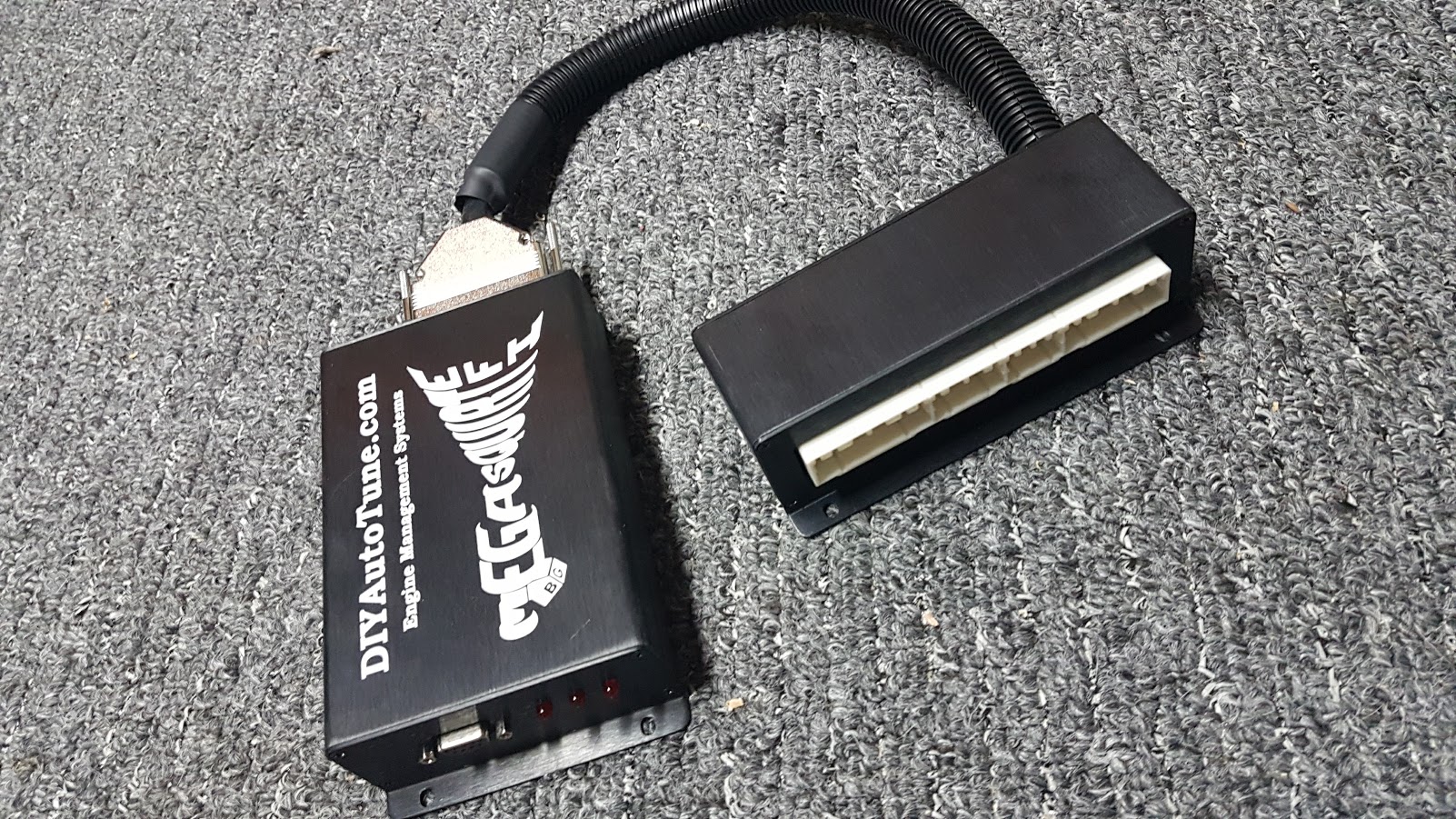
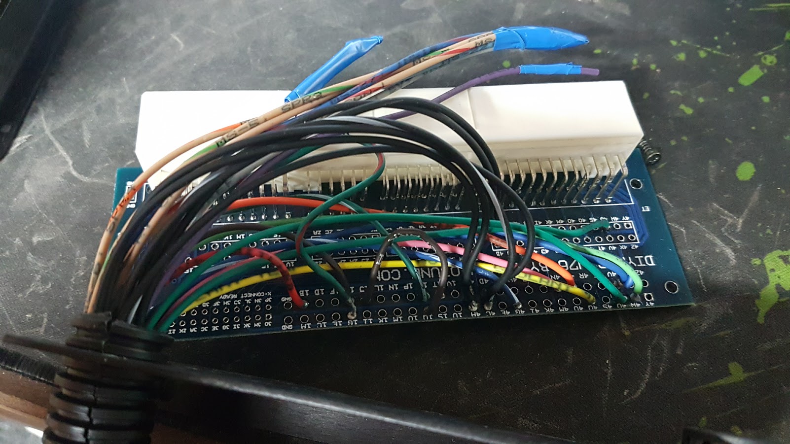
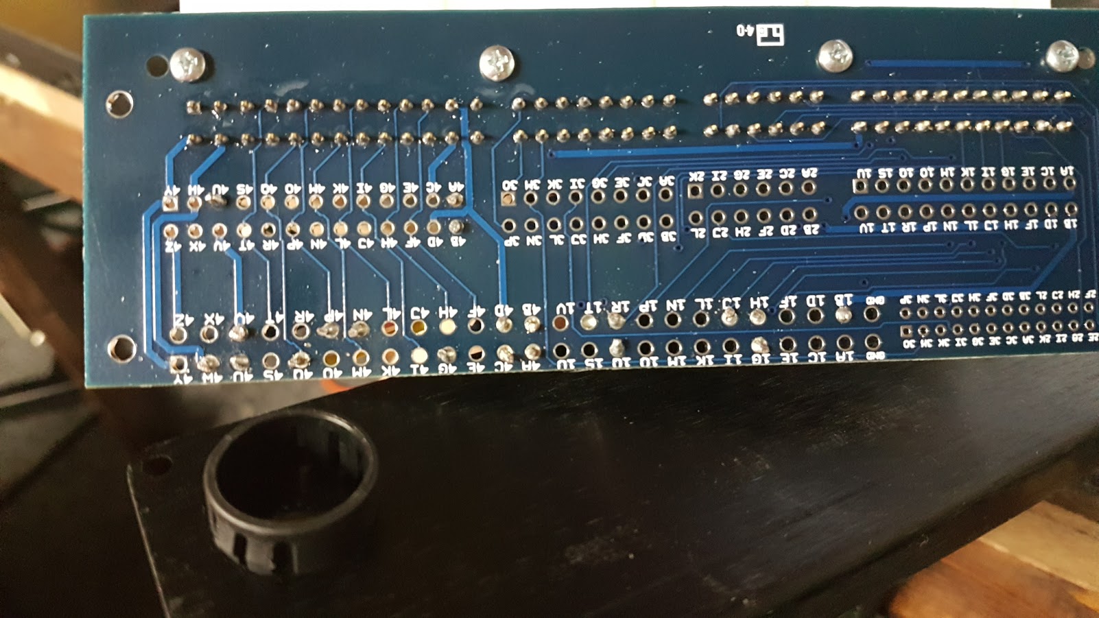
Here is some pictures of the board and what i have done any help is help Thanks!

**Bonus Question**
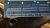
here is the wiring diagram i used for the pigtail and the 72pin BOB is this right for a 91 1.6L miata
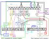
my wiring
I would first like to say i think i may have messed up and any help or thoughts are welcome!
Items:
- MegaSquirt-II Programmable EFI System PCB3.0 � Kit
- DIYBOB Breakout Adapter � Nippon Denso 76 pin
- 24″ MegaSquirt Pigtail Harness
- 91 1.6L na miata
- 11.1 V 20c 24.42wh 2200mah battery
* all items were bought from DIYautotune
i am pretty confident in my soldering skils and i am not able to find any problem in a soldering issue.
i followed these instructions
Assembly Guide - MegaSquirt(R) V3.0 Main Board
on step 50. i followed the Hall/Optical/ect. path thinking that is what the 1.6 miata uses for tack (first thing im probably wrong at)
Step 69. i did not do this step because i didnt think it applied (probably wrong again!)
Step 71. current limit circuit for driver FET protection (i did this) seamed legit!
at this point i was done soldering the kit so i decided to fire it up on the desk to see if i could use it was tuner studio.
I applied power (11.1V) to pin 28 on the DB37 plug using the pigtail (red wire that said power)
and for ground i used about 3-4 of the ground wires (assuming there all connected) and 3- 4 was all i could fit in my battery.
pic of the battery i used
when i applied power for the fist time smoke came from the right side of the board.
picture from where the smoke came from
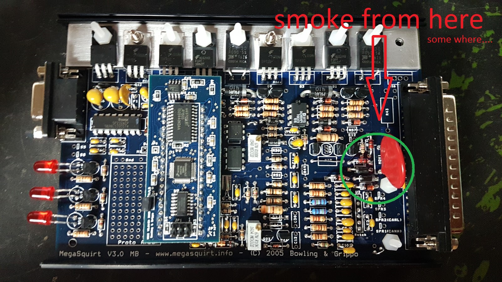
i thought the MOV1 blew so i replaced the Metal Oxide Varistor (MOV1) and i havent been able to get it to power on ever ever scene.
Here is some pictures of the board and what i have done any help is help Thanks!

**Bonus Question**
here is the wiring diagram i used for the pigtail and the 72pin BOB is this right for a 91 1.6L miata
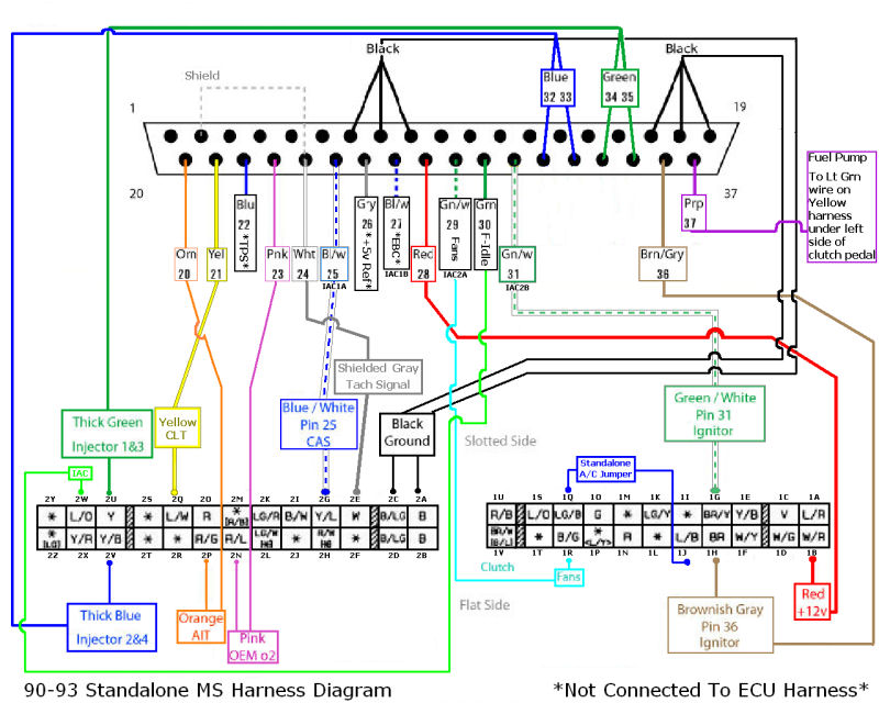
my wiring
Reply
 0
0

0


Junior Member
Joined: Dec 2016
Posts: 92
Total Cats: 1
From: Jax, FL
Quick question. I'm building the same thing you are, and I'm getting kinda lost with the different ways of achieving the ignition input and output in the Miata.
Maybe I'm getting confused here, but if I follow the "How to megasquirt your miata" from DIYautotune, it says the following:
CKP: DB pin 24
CMP: DB pin 5
Spark A: pin 36
Spark B: pin 6.
But following the diagram posted in this thread, in pin 24 I'd have "Tach signal", pin 5 is empty, pin 36 goes to the ignitor and pin 6 is empty too.
So I guess that one setup uses the SPR pins and the other one uses the IAC stepper pins for the second spark and the CMP?
Last edited by Nicolas L; Jan 19, 2017 at 01:15 PM.
Reply
0
0
Thread Starter
Newb
Joined: Nov 2016
Posts: 6
Total Cats: -4
so im about to order anther cap for c17. can anyone else think of anything else i should test or should order?
Reply
0
0
Junior Member
Joined: Dec 2016
Posts: 92
Total Cats: 1
From: Jax, FL
Did you ever get this running? At some point I was pretty sure about what I had to do to my MS2 to get it running (It was built for something else), but after I moved my brain did a reset apparently and I don't remember ****. If yours is running then I know what's what
Reply
0
0


