
DLP-TXRX-G internal USB adapter with DIYPNP


Thread Starter
Junior Member
Joined: Feb 2011
Posts: 51
Total Cats: 2
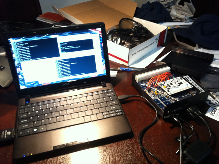
Hi all! I recently ordered my DIYPNP to power my 1.8L Miata, which is currently supercharged. I soldered everything yesterday and today, went ahead and fully populated the main board except for the cam control circuit and I must say I am very happy with my work so far.
I bought the DLP-TXRX-G USB adapter from DIY in the hopes of replacing the serial port entirely on my DIYPNP, but now that I have it in my hands and am researching how to wire it to the board I am unsure whether anyone has ever done this before.
The instructions on DIY's site are for a standard MS build with no references to the DIYPNP board. I'm no electrical engineer - I can figure some things out, but in this case I need to be pointed in the right direction. The reason I want to install the DLP USB adapter is that I'm using a netbook which has no serial ports and I would trust this, assuming I can wire it properly, over the DB9 connector with an external adapter.
I searched the board but nothing specific came up. I'm going to contact them but seeing as it's now Friday evening I don't expect to hear back until next week.
Any help would be greatly appreciated! Thanks!
Reply
 0
0

0

Hi all! I recently ordered my DIYPNP to power my 1.8L Miata, which is currently supercharged. I soldered everything yesterday and today, went ahead and fully populated the main board except for the cam control circuit and I must say I am very happy with my work so far.
I bought the DLP-TXRX-G USB adapter from DIY in the hopes of replacing the serial port entirely on my DIYPNP, but now that I have it in my hands and am researching how to wire it to the board I am unsure whether anyone has ever done this before.
The instructions on DIY's site are for a standard MS build with no references to the DIYPNP board. I'm no electrical engineer - I can figure some things out, but in this case I need to be pointed in the right direction. The reason I want to install the DLP USB adapter is that I'm using a netbook which has no serial ports and I would trust this, assuming I can wire it properly, over the DB9 connector with an external adapter.
I searched the board but nothing specific came up. I'm going to contact them but seeing as it's now Friday evening I don't expect to hear back until next week.
Any help would be greatly appreciated! Thanks!
I bought the DLP-TXRX-G USB adapter from DIY in the hopes of replacing the serial port entirely on my DIYPNP, but now that I have it in my hands and am researching how to wire it to the board I am unsure whether anyone has ever done this before.
The instructions on DIY's site are for a standard MS build with no references to the DIYPNP board. I'm no electrical engineer - I can figure some things out, but in this case I need to be pointed in the right direction. The reason I want to install the DLP USB adapter is that I'm using a netbook which has no serial ports and I would trust this, assuming I can wire it properly, over the DB9 connector with an external adapter.
I searched the board but nothing specific came up. I'm going to contact them but seeing as it's now Friday evening I don't expect to hear back until next week.
Any help would be greatly appreciated! Thanks!
With the 50 pin header pointing UP, and the processor on the top, do you see the 16 pin SMT IC in the upper right-hand corner of the board? I'm pretty sure thats it (I'm just going off of pictures, I don't have a microsquirt in front of me,but I can check when I get home in a couple of hours if nobody has chimed in)
This guy:

Assuming I'm correct on that part, the process would be roughtly the same as the directions for the standard megasquirt, but, you know, quite a bit more challenging and delicate since soldering wires onto those tiny pads would be difficult and the odds of you ripping them off the board would be high.
Reply
0
0
Thread Starter
Junior Member
Joined: Feb 2011
Posts: 51
Total Cats: 2
Man, that's disappointing. I definitely don't want to touch anything on the Microsquirt module. I made the mistake of skimming the instructions on the DIY website when I ordered because I wasn't fully aware of the differences between the setups and assumed that the instructions also applied to the DIYPNP kit I was ordering (plus I was talking about it with a friend of mine who said "Oh, yeah, that's the same thing as in a serial to USB dongle, you should just be able to replace the DB9 connector with it." Thanks friend!). I still don't understand all the differences between the various MS options.
I'd like to think that I shouldn't HAVE to buy the serial->USB adapter dongle that DIY sells and that there are other options out there that might work.. true?
I live in Puerto Rico so it can be a big hassle getting things... I either have to order online and wait a week or hope Walmart has it.
In any case, thank you Jeff.
Reply
0
0
Man, that's disappointing. I definitely don't want to touch anything on the Microsquirt module. I made the mistake of skimming the instructions on the DIY website when I ordered because I wasn't fully aware of the differences between the setups and assumed that the instructions also applied to the DIYPNP kit I was ordering (plus I was talking about it with a friend of mine who said "Oh, yeah, that's the same thing as in a serial to USB dongle, you should just be able to replace the DB9 connector with it." Thanks friend!). I still don't understand all the differences between the various MS options.
I'd like to think that I shouldn't HAVE to buy the serial->USB adapter dongle that DIY sells and that there are other options out there that might work.. true?
I live in Puerto Rico so it can be a big hassle getting things... I either have to order online and wait a week or hope Walmart has it.
In any case, thank you Jeff.
I'd like to think that I shouldn't HAVE to buy the serial->USB adapter dongle that DIY sells and that there are other options out there that might work.. true?
I live in Puerto Rico so it can be a big hassle getting things... I either have to order online and wait a week or hope Walmart has it.
In any case, thank you Jeff.
In defense of your friend, he isn't actually wrong, lots and LOTS of usb->serial adapters use the FTDI chip.
Come to think of it, you could probably get away with building a level shifter between the FTDI and the MAX232 tx and rx lines. No guarantees though.
Reply
0
0
Thread Starter
Junior Member
Joined: Feb 2011
Posts: 51
Total Cats: 2
Did I mention I'm no electrical engineer?  I'm actually an avionics technician but my job does not include troubleshooting to the component level. I'm experienced at soldering but have never actually built up a PCB with components so I've been having fun with the idea of running my car on a computer I put together myself, if not engineered myself.
Maybe my friend could figure out how to build a level shifter, but I'm probably better off just soldering in the DB9 and using a dongle adapter. If I had just ordered that stuff from DIY I'd be loading firmware right now. Here's hoping I can find a good quality dongle this weekend so I can keep making progress!
Thanks again. Looking forward to sharing my success stories instead of just asking for help.
I'm actually an avionics technician but my job does not include troubleshooting to the component level. I'm experienced at soldering but have never actually built up a PCB with components so I've been having fun with the idea of running my car on a computer I put together myself, if not engineered myself.Maybe my friend could figure out how to build a level shifter, but I'm probably better off just soldering in the DB9 and using a dongle adapter. If I had just ordered that stuff from DIY I'd be loading firmware right now. Here's hoping I can find a good quality dongle this weekend so I can keep making progress!
Thanks again. Looking forward to sharing my success stories instead of just asking for help.
Reply
0
0


Sorry to hear about the confusion. I will try to remember on Monday to see how I can edit the DLP's listing to make things a bit more clear. You technically should be able to install it on a DIYPNP, but it would take above-average soldering skills. We've not tried to do so, and I'm unaware of anyone else who has attempted.
If you need to order a new dongle, we carry a good, low cost one. We can ship it USPS Priority, so it would get to you in 2 days for cheap.
If you need to order a new dongle, we carry a good, low cost one. We can ship it USPS Priority, so it would get to you in 2 days for cheap.
Reply
0
0
Thread Starter
Junior Member
Joined: Feb 2011
Posts: 51
Total Cats: 2
Well I ended up making a last-minute run to Radio Shack, after a confusing conversation in Spanglish I came away with a dongle (far more expensive than the one you sell Ben) but I plugged it in, my netbook immediately downloaded the drivers, and with bated breath I fired up the DIYPNP on a 12v power supply and... success!
I installed the latest firmware with no problems and successfully connected to the MS ECU with TunerStudio and Megatune. Time for a beer.
I installed the latest firmware with no problems and successfully connected to the MS ECU with TunerStudio and Megatune. Time for a beer.
Reply
1
1

Thread Starter
Junior Member
Joined: Feb 2011
Posts: 51
Total Cats: 2
I went back and wired in a circuit for the 02 sensor on the DB15 connector using Brain's suggestion like this.
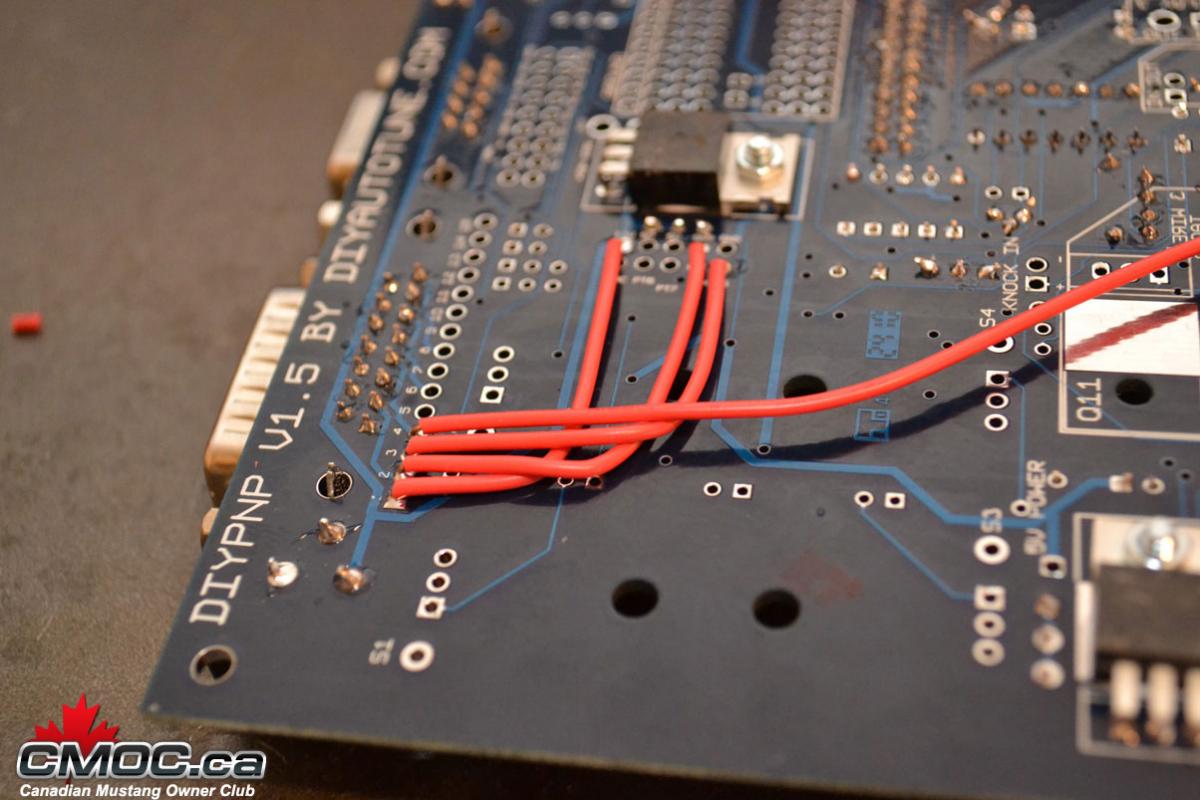
I removed the wire from the O2 pin on the main board to the adapter board so I am committed to starting up with the WBO2 sensor from the get go. I am going to install it in the stock O2 sensor location because I don't have a hot turbo to worry about.
Fabbed up a mounting bracket to bolt the DIYPNP box in the stock ECU location. I am getting closer.
Things left to do:
-Install WBO2 sensor and solder the wiring into the DB15 connector
-Install IAT sensor in my intake plumbing, should be very easy as my JRSC has a plastic pipe, just drill and thread in. Run IAT wiring
-Remove MAF
-Run vacuum hose for MAP sensor
I am using an Innovate MTX-L wideband controller and integrated gauge. I'm not 100% sure if I can run the ground into the DB15 connector (considering I wired up a ground there) or if I need to actually run it to the main ground on the engine? I know this is critical.
Reply
0
0
Thread Starter
Junior Member
Joined: Feb 2011
Posts: 51
Total Cats: 2
I plugged the MS EMS into the car and turned on the ignition to check that it would at least power up, all seemed well except the fan came on immediately and there was a configuration error with tach reading 65,000+ RPM. That obviously isn't right so I went back and read up some more. Turns out I didn't understand the grid on the DIY website and had just wired PA0 straight up to pin A1 on the connector board. Figured out what I was supposed to do and connected PA0 -> Relay 1 IN and Relay 1 OUT to A1.
The documentation on how to configure the output is still really lacking in clarity but I think I've got this right:
Output port settings: PA0 (Knock Enable):
Enabled
Power on value: 0
Trigger value: 1
Output channel: coolant >
Threshold: 200
Hysteresis: 10
The documentation on how to configure the output is still really lacking in clarity but I think I've got this right:
Output port settings: PA0 (Knock Enable):
Enabled
Power on value: 0
Trigger value: 1
Output channel: coolant >
Threshold: 200
Hysteresis: 10
Last edited by QWKDTSN; Feb 4, 2012 at 08:23 PM.
Reply
0
0
Thread Starter
Junior Member
Joined: Feb 2011
Posts: 51
Total Cats: 2
Just plugged the ECU back into the car and the config error is gone as I'd hoped (clearly caused by the PA0 connection error I made).
I was able to calibrate the TPS and all the gauges look good. Still haven't tried to crank or do anything... Too many things left to do. I will basically be doing the WB02 sensor installation, MAF delete, and IAT sensor installation at one time and then making sure all my settings are right prior to trying to crank the car. That will probably take most of a day so it likely won't happen until next weekend.
BTW I'd like to change the thread title to something like "JRSC DIYPNP build" because my initial question has been answered, but I don't want to create another thread. I'm going to carry on posting updates because it helps me think and gives me a good place to ask any further questions that come up. If a mod could do that I'd appreciate it.
I was able to calibrate the TPS and all the gauges look good. Still haven't tried to crank or do anything... Too many things left to do. I will basically be doing the WB02 sensor installation, MAF delete, and IAT sensor installation at one time and then making sure all my settings are right prior to trying to crank the car. That will probably take most of a day so it likely won't happen until next weekend.
BTW I'd like to change the thread title to something like "JRSC DIYPNP build" because my initial question has been answered, but I don't want to create another thread. I'm going to carry on posting updates because it helps me think and gives me a good place to ask any further questions that come up.
If a mod could do that I'd appreciate it.
Reply
0
0
Thread Starter
Junior Member
Joined: Feb 2011
Posts: 51
Total Cats: 2
So... I've been thinking about it... Can someone please tell me if this would work or not?
I know the ground for the WB02 sensor is very important and should be connected to the same ground as the ECU. I know many folks have used the main bonding point on the front of the engine (throttle body side).
However I have wired up the DB15 connector on the DIYPNP box as Brain recommended but I have been searching for several hours and still don't have a satisfactory answer about this - though I don't see why it wouldn't work.
-Install MTX-L gauge in dash. Solder together a harness extension through the dash and passenger sill (or center console, now that I think of it.. hmm) and terminate with the female DB15 connector with the MTX-L's power, ground, and signal wires going into pins 1, 2 and 4. I will install an inline 5 amp fuse capsule on the power wire a few inches from the DB15 connector.
Sound like a solid plan? If grounding the WB02 directly to the ECU isn't a good idea, please let me know.
Reply
0
0
Thread Starter
Junior Member
Joined: Feb 2011
Posts: 51
Total Cats: 2
Thank you very much Jeff, that will make my life a lot easier! I thought it should work but couldn't find anything anywhere to confirm the suspicion and I want to make everything as trouble- and worry-free as possible. I hate routing wires all over the place.
I think I might be able to get the car started up sooner than I had anticipated - just need to source a pipe for the MAF delete and spend some time working on the physical aspects of the car.
I currently have the MM9697 base map from DIY loaded with various variables adjusted for my setup and I'm hoping it will at least fire up and idle so I can start carefully driving around.
My car is a 1996 1.8L with M45 supercharger, smaller pulley and JR header/Borla exhaust. Fueling is stock. Spark is colder NGK plugs and wires. Planning on upgrading injectors once I have it started up and running. My biggest concern with tuning is the timing map...
I'm living in Puerto Rico (in the military) but don't speak much Spanish.... enough to order food but not enough to navigate a tuning session with a shop, although there are many competent shops on the island. Just another hurdle I hope to clear...
Reply
0
0
Thread Starter
Junior Member
Joined: Feb 2011
Posts: 51
Total Cats: 2
Today I installed my IAT sensor in my Jackson Racing supercharger crossover pipe. I was pleased to find that the plastic was very thick as I'd been hoping to just tap the IAT sensor directly into the plastic. I marked and drilled and carefully enlarged the hole until I could firmly thread in the sensor. I built up the connector and ran the wires over and ziptied them off for now.
I installed my MTX-L wideband gauge in the passenger side center eyeball and ran all the wires through the dash, down the passenger sill and tucked them out of the way. I need to pick up a fuse block tomorrow and then I can finish the wiring of the DB15 connector for the wideband. After that I will be much closer to firing the car up.
Things still left to do:
-Finish wideband wiring on DB15 connector
-Install WB02 sensor and run wiring from the engine bay into the dash to connect to the back of the MTX-L gauge
-Remove the JRSC Powercard, including wiring and vacuum line
-Run new MAP vacuum line down the passenger sill to the new DIYPNP ECU
-Remove MAF sensor, replace with a straight section of pipe, wire GM IAT sensor into MAF wiring harness and tidy up
-Check, double-check and triple-check my MS settings
-Hopefully fire up and get it to idle...
Reply
0
0
Thread Starter
Junior Member
Joined: Feb 2011
Posts: 51
Total Cats: 2
Done done and done!
Got the long checklist completed today. The hardest part was getting the old O2 sensor out. What a b*tch. Heating the header with a heat gun for a few minutes finally allowed it to loosen up. I got the wideband all installed and everything else done and..
It fired up on the first crank! After a slight stutter it settled into a smooth 950RPM idle. I didn't quite expect that even though the map is supposed to be pretty much ready to go for a stock car. I went to set the timing with the trigger wizard and it kept stalling out on me, so I didn't want to wake the neighbors at 3 AM with continual restarts and throttle blips, and am content to have a couple of beers and get to work on it in the morning.
Reply
1
1
Thread Starter
Junior Member
Joined: Feb 2011
Posts: 51
Total Cats: 2
My timing was so far out that I had to manually rotate the CAS because I couldn't figure out which way to go on the Trigger Wizard. Got it set perfectly. My big concern was that the wideband O2 sensor was not talking to the ECU. Turns out the signal wire was slightly unseated in the connector I wired in. I input my .22-5v settings and the wideband gauge and TunerStudio now agree on the dot. Success!
I took it for a quick, very gentle spin around the block and it drives like stock. A/F ratios showed slightly rich. Looking forward to getting some bigger injectors and getting it all dialed in!
I took it for a quick, very gentle spin around the block and it drives like stock. A/F ratios showed slightly rich. Looking forward to getting some bigger injectors and getting it all dialed in!
Reply
0
0
Thread Starter
Junior Member
Joined: Feb 2011
Posts: 51
Total Cats: 2
Thanks! Things are going well. I just did an extended autotune section that covered most of my map. I am using all of the default autotune settings (cell change resistance normal, default authority limits) but I added an 1100 RPM filter to keep it from messing with my idle (any more than it already did).
Everything is going well so far, except I definitely need bigger injectors (already on their way). Max duty cycle was 97% during my run. The car is running noticeably better than it ever did with the stock ECU and Powercard. I am using DIY's base ignition map and autotuning for their base A/F map.
The only issue I'm really having is with the car wanting to stumble when coming up to a stop sign. As I decelerate down to walking speed and push in the clutch the revs fall and almost die, then cycle a few times. It didn't do this when using the DIY base map, I think I made the mistake of allowing the autotune too much freedom in the low RPM ranges (although I now idle at a nice 14.6/1 vs. the super rich idle I had before). Going to try to smooth out that area manually.
Any suggestions on keeping the revs from dipping below 800 other than VE table hammering?
Reply
0
0


