
Doing MS3x on a stock 91


Thread Starter
Junior Member
Joined: Nov 2012
Posts: 72
Total Cats: 2
From: Safety Harbor, FL
Like I said, the output is behaving. The input is being weird. Is there something different about the Nitrous Input?
BTW, I have discovered intermittency that might explain the problem with Frank's msq. Car was running GREAT this afternoon. This evening, it's back to intermittent starvation and stuttering. I found a leaky injector seal... Maybe affecting fuel pressure?
BTW, I have discovered intermittency that might explain the problem with Frank's msq. Car was running GREAT this afternoon. This evening, it's back to intermittent starvation and stuttering. I found a leaky injector seal... Maybe affecting fuel pressure?
Reply
 0
0

0
Thread Starter
Junior Member
Joined: Nov 2012
Posts: 72
Total Cats: 2
From: Safety Harbor, FL
Another FYI tidbit:
There's a jumper JP8 on the MS3x that can be put in place to change the Nitrous Input from a 12v to a Gnd switching input.
Megasquirt-3 MS3 Hardware Manual
If I hadn't already rewired my connector to use the Launch Input last night, I might have done that instead. Good to know, anyway.
There's a jumper JP8 on the MS3x that can be put in place to change the Nitrous Input from a 12v to a Gnd switching input.
Megasquirt-3 MS3 Hardware Manual
If I hadn't already rewired my connector to use the Launch Input last night, I might have done that instead. Good to know, anyway.
Reply
0
0
Thread Starter
Junior Member
Joined: Nov 2012
Posts: 72
Total Cats: 2
From: Safety Harbor, FL
Probably. It's still a good piece of info for the person who may be using or planning to use all of those other inputs.
Hey, has anybody ever used the 12v supply from the purge valve as power for their WB02? I was looking for an easy way to wire that... and that looks like a no-brainer. It's on the same circuit as the ECU and injectors. Put a 5A fuse inline to keep O2 shorts from blowing the main ECU fuse... should work, right?
Hey, has anybody ever used the 12v supply from the purge valve as power for their WB02? I was looking for an easy way to wire that... and that looks like a no-brainer. It's on the same circuit as the ECU and injectors. Put a 5A fuse inline to keep O2 shorts from blowing the main ECU fuse... should work, right?
Reply
0
0

Joined: Sep 2005
Posts: 34,433
Total Cats: 7,549
From: Chicago. (The less-murder part.)
Can't imagine why not. The wideband does not require a lot of current, and it doesn't matter is there's a small amount of offset in the supply between the ECU and the wideband controller.
Ideally, thou shalt ground the wideband controller to the same point as the ECU, and as near to the ECU as possible. For a MS, this is typically achieving by grounding the sensor directly to one of the unused GND pins at the DB37 connector on the main board.
In the case of the Spartan, this would be the black wire, which is the "electronics ground". (The white wire, which is heater ground, can go anywhere.)
On the other hand, you already have to run some wire from the sensor to the ECU, and it might just be simpler to run all wire from the sensor to the ECU, rather than splitting the harness out and grabbing different signals at different places.
Reply
0
0
Thread Starter
Junior Member
Joined: Nov 2012
Posts: 72
Total Cats: 2
From: Safety Harbor, FL
Brain, I'm using the new Spartan sensor that has the controller circuit built into the connector. There is no separate controller.
http://www.14point7.com/Support/Soft...ser_Manual.pdf
And I just realized it has two outputs. I thought it was WB only. Nice!
http://www.14point7.com/Support/Soft...ser_Manual.pdf
And I just realized it has two outputs. I thought it was WB only. Nice!
Reply
0
0
Thread Starter
Junior Member
Joined: Nov 2012
Posts: 72
Total Cats: 2
From: Safety Harbor, FL
My initial logic was that there's already an O2 sensor wire going to the ECU, and sensor grounds going to the ECU from under the hood. I could reuse those easily enough, just need a source for power from under the hood. No running of extra wires, no splicing into the ECU.
However, since my new WBO2 has an NB output, I'll probably go ahead and use that for the NB output to retain stock ECU backward compatibility. Which means I need to run a sensor wire to the ECU at the very least.
Joe's idea of just running a bundle of spare wires through the firewall for various and sundry purposes is seeming like a better and better idea.
Reply
0
0
Joined: Sep 2005
Posts: 34,433
Total Cats: 7,549
From: Chicago. (The less-murder part.)
From the downpipe, it's a pretty straight shot around the transmission and up the shift boot, and from there it's just straight across the dashboard to the ECU.
Reply
0
0
Thread Starter
Junior Member
Joined: Nov 2012
Posts: 72
Total Cats: 2
From: Safety Harbor, FL
Sounds promising. Still waiting on the WB to show up.
Thinking about heading to the salvage yard and raping a 12-pin connector from something to plug into one of the unused slots on my DIYBOB connector. Would make for much easier "non-stock" connections.
(why didn't I think of that last week when I was there?)
Thinking about heading to the salvage yard and raping a 12-pin connector from something to plug into one of the unused slots on my DIYBOB connector. Would make for much easier "non-stock" connections.
(why didn't I think of that last week when I was there?)
Reply
0
0
Thread Starter
Junior Member
Joined: Nov 2012
Posts: 72
Total Cats: 2
From: Safety Harbor, FL
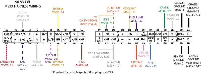
Even after switching the input, my AC is still acting wonky. Sometimes it works, sometimes it doesn't.
But, I think I've figured out why. The stock 1991 wiring switches both the AC relay and the fan relay on activation of pin 1R. My setup (please don't give me any more **** about this, *I* didn't wire it this way, and it was supposedly working in a 1994... though I never asked if his AC was functional) has 1R connected to a "medium current" output, which surely has enough current to trigger one relay... but might not be sufficient to trigger two in series.
A project for another day. I've got injector seals to swap out to stop a fuel leak and stabilize my fuel pressure. (I knew #4 was leaking... but didn't realize how much until I opened the hood with the engine running a while ago... it is SPEWING fuel!)
Reply
0
0
I told you to use an injector output.
I feel like putting all this time/money/effort back in March of 2010 into being one of (if not) the first to run ms3x on a miata and finding out best practices to spread wisdom to all my minions was just wasted effort.
also, 1R is the main cooling fan. 1J is the a/c compressor and a/c fan relays. could THAT be the issue?
Reply
0
0
Thread Starter
Junior Member
Joined: Nov 2012
Posts: 72
Total Cats: 2
From: Safety Harbor, FL
I asked you not to give me any more **** about it.
If I had built the thing, I'd have followed all of your best practices. And as I'm fixing things, I'll be following them. But, this thing was built by someone else and I was led to believe that it was 100% functional, so I saw no reason to change anything other than what was required to wire it to my 91.
As I'm learning that is not the case, I'm fixing it where it needs fixing.
Lest you think that I don't know how to search, or who the "go to" guys are, I've already found this thread with great AC and Fan wiring info:
https://www.miataturbo.net/megasquir...-verify-67046/
I'll get there, man. Your efforts are appreciated.
Reply
0
0

Thread Starter
Junior Member
Joined: Nov 2012
Posts: 72
Total Cats: 2
From: Safety Harbor, FL
Wiring pinout saved. I've seen several similar to that one, but I'm not sure they were exactly the same. (there's one that came in the box with my MS3, even)
Oh, and I have 1R and 1J correctly wired. I just had 1R on the brain because that's the one I had to move (it was on 1L for the '94).
Will make some decisions on how to pinout the 12-pin connector for the WB02... and extra injector outputs... and... what other future-planning should I do?
At this point, I'm not planning on doing sequential spark. I haven't found a good reason to do it yet. I won't be adding boost. Is it worth doing for an NA application?
I guess it would be wise to go ahead and pin-out the remaining extra input and outputs just to have them at the ready. Hmmm... maybe I should use the 16-pin rather than the 12?
Reply
0
0


