
EBC Not Working


Other way around. A constant ground would cause the valve to be 100% closed (as soon as switched power is applied). This is what he's seeing. Diagnosed that some months ago. Needs to use a multimeter to find the short.
Reply
 0
0

0


Thread Starter
Junior Member
Joined: May 2010
Posts: 280
Total Cats: 0
From: Darlington, UK
There is no short on the wire of the ebc. I have traced the full length of them. I was wondering if the wire on the db connector may have been mislabelled so the wire which it is currently connected to which is supposed to be ebc may actually be ground and vice versa. If that is the case then that's what the issue is.
I do have a multimeter but I have no idea what settings to set it and where to test.
I'm seeing over boost as the valve is locked shut and doesn't open
I do have a multimeter but I have no idea what settings to set it and where to test.
I'm seeing over boost as the valve is locked shut and doesn't open
Reply
0
0
You can use either the ohms or diode continuity setting on your multimeter. I like diode continuity because it usually gives a beep. Put your black multimeter lead to chassis ground, and use the red lead to probe. If using ohms, a short will show a very low resistance, and open will show very high resistance. If using diode continuity, a short will beep, an open will not.
Pretty basic stuff. Surely, there's someone there that can give you an intro to your multimeter, or there's something you can find online (maybe youtube). It may seem like a lot at first, but once you see it in action, it will quickly make sense.
BTW, you can't say there's no short on the wire. Only the multimeter can tell you that. Your eyes can lie.
Reply
0
0
Thread Starter
Junior Member
Joined: May 2010
Posts: 280
Total Cats: 0
From: Darlington, UK
Ok so I went to a guy I know with a multimeter and we tested the wires to the ebc and there was definatley no short. This guy has experience with tuning ecu's so we had a play about but something strange has happened.
Previously the EBC would be closed as soon as the ignition was switched on and no matter what settings we adjusted the valve did not open. So this time we tried to connect the ebc to the earth of the DB connector which goes into the ecu just to check that the EBC signal wire had not been mislabelled as EBC. This never made a difference and the wires do appear to be as labelled. Hence the EBC wire is the signal wire for the EBC.
But than the valve opened and now wont close. We again checked the EBC with a multimeter and power is going through the EBC as if you connect the wire to earth which goes to the EBC wire of the ECU the valve closes. But reconnect the wire to the EBC signal wire of the ECU which it has always been connected and the valve is now not functioning as if the EBC signal wire is no longer signalling.
Im not sure what the fault is. The only thing I can now think is that the ECU its self is actually faulty and the EBC wire is not working properly and is or was possibly shorting.
Any suggestions as as much as I really want EBC im starting to get fed up and thinking of doing without it.
Reply
0
0
Thread Starter
Junior Member
Joined: May 2010
Posts: 280
Total Cats: 0
From: Darlington, UK
FINALLY!! Some progress.
I tuned the open loop table like the table in Braineacks link from page 1 of this thread and the vavle started to operate. at no throttle with the value set to 100 the valve is completly open.
If I change the value to 20 the valve closes. FINALLY.
This only works if I leave the settings set to open loop. As soon as I switch the boost settings to closed loop the valve just stays closed. So I take it I leave the settings as open loop.
Now whats next?
Does Closed loop still need the table changing? The table at present is set to 100 for 0 throttle, then 110 for 20% and then 156 for 40%, 170 for 60%, then 201 for all the other throttle positions.
Is it just the case now that I leave this table and start playing with the open loop table until I get the boost I need? Adjusting the figures up and down accordingly?
Reply
0
0
Thread Starter
Junior Member
Joined: May 2010
Posts: 280
Total Cats: 0
From: Darlington, UK
Ok,
So when everything is running should the boost settings be set to closed loop or open?
I used the table from your link should this now be left the same. Which table is the table that needs to be adjusted to get the required boost?
Or do you have to do both?
when going back to closed loop no matter what the value is (0, 100, 200, 400) the valve stays shut. Should the table be tuned and then do you need to change back to open loop for the valve to work?
Reply
0
0
the closed loop table should be the kPa values you want to hit. so say you're looking fro 15psi, you'd plug 205kPa in there.
then you have to tune the PID settings in order for the valve/software to react.
read through this: http://msextra.com/doc/ms3/Boost_Control.html
then you have to tune the PID settings in order for the valve/software to react.
read through this: http://msextra.com/doc/ms3/Boost_Control.html
The next step after setting up the target table and supporting settings is to tune the PID gains:
Set Integral and Differential Gains to 0% - To make tuning the Proportional gain easier, set the Integral and Differential gains to 0%.
Set Proportional gain to 100% and slowly lower - While tuning Proportional gain, higher numbers mean slower boost climb and lower final boost. For safety, start with a very high gain (100% should be sufficient). Find the RPM that typically spools quickly, and fully and quickly depress the accelerator. Note how much boost is reached. If boost overshoots the target dramatically, increase the Proportional gain. Otherwise, reduce the Proportional gain and try again. Do this until boost reaches the target with a small amount of overshoot.
Tune the Integral Gain - The next step after the target is reached consistently is to tune the Integral gain. Starting from the RPM used to tune the P-gain, fully depress the accelerator and watch the boost as the engine climbs through the RPM range. As the engine accelerates through the rev range, the boost will probably creep away from the target. Keep increasing the I gain until the controller adequately maintains the target with minimal oscillation. It may be necessary to increase the P gain a bit after tuning the I gain since the two gains tend to counteract each other.
tune the Derivative Gain - Increase the D gain until the overshoot is minimized. Care must be taken when increasing the D gain as too much D gain can over-dampen the effects of the P and I gains.
Reply
0
0
Thread Starter
Junior Member
Joined: May 2010
Posts: 280
Total Cats: 0
From: Darlington, UK
Ok,
I think I get it now. I need to set P then the other values etc now.
But do you set these values with the settings burned as Closed loop or open as in open loop it would appear to work but in closed loop it will most likely cause the valve to remain closed no matter what is done to the P values.
Eg assuming your cars are all correct and running on EBC if you look at your boost settings now does it say closed loop or open loop?
Reply
0
0
Thread Starter
Junior Member
Joined: May 2010
Posts: 280
Total Cats: 0
From: Darlington, UK
To be honest no I don't really understand the difference. I have set both the tables closed and open to the same as the link you posted. When in open loop if I adjust the values in the table the valve opens and shuts but in closed loop changing the values has no effect on the valve in terms of been able to blow through it or not. The valve now functioning is a step forward as its just a case of setting the software. Trouble is the guides are not simplistic enough and they assume that you understand certain terminology which if you don't understand makes it difficult.
Reply
0
0
open loop just runs are whatever duty cycle you tell it to in your open loop table.
the numbers you are inputing are the duty cycles in which to drive the valve at a particular TPS position and RPM.
closed loop takes live readings (boost in the case) and maniplautes the solenoid's duty cycles in order to maintain the boost against the closed loop table.
the numbers you are inputting are the boost targets you want to hit at a particular TPS position and RPM.
it works like like your ARF targets and autotune and/or EGO.
the PID control is an algorithm that controls how the bost target is manitained, you have to go through all the trial and error in tuning the PID values in order to get your solenoid to react properly and maintain/reach the boost targets in your closed loop table. Once properly tuned, you can then pretty much change the closed loop table to whatever number you want, and the code will achieve those targets.
for instance, if your P value is too high, you'll never see any reaction in the solenoid.
if the P value is too low, you'll overshoot your boost target.
Reply
0
0
Thread Starter
Junior Member
Joined: May 2010
Posts: 280
Total Cats: 0
From: Darlington, UK
Ok that's a great explanation I get that. Are the 2 tables in the link a good reference table to then start setting p?
I know that the max value in the closed loop will limit the boost I achieve but other than that are they a good base?
Only other thing is I take it that to adjust p I need to have both the tables set which they now are and then burn it with it set to closed loop?
I know that the max value in the closed loop will limit the boost I achieve but other than that are they a good base?
Only other thing is I take it that to adjust p I need to have both the tables set which they now are and then burn it with it set to closed loop?
Reply
0
0
yeah looks like you're aiming for 15psi at WOT.
i'd move the freq of the valve to 34.5Hz, using the square solnoid from DIY?
start lowering P, you'll probably have to take it close to 30-20 or so before the boost starts going over wastegate. follow the directions in that link i posted, has a rudimentary how-to tune.
i'd move the freq of the valve to 34.5Hz, using the square solnoid from DIY?
start lowering P, you'll probably have to take it close to 30-20 or so before the boost starts going over wastegate. follow the directions in that link i posted, has a rudimentary how-to tune.
Reply
0
0

Thread Starter
Junior Member
Joined: May 2010
Posts: 280
Total Cats: 0
From: Darlington, UK
No it's a combination of things. I think the problem is that everything needs to be correct or it simply won't work. I tried loads of different things but it wasn't correct. I believe it is correct now but won't know for sure until this weekend when I have a play with the values.
Reply
0
0

Newb
Joined: Feb 2012
Posts: 44
Total Cats: 8
Don't mean to crowd this thread so let me know so I can start a new thread.
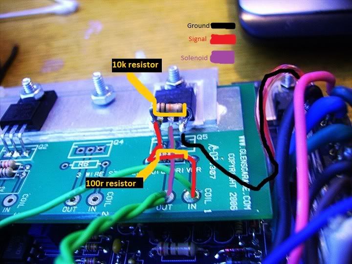
I checked resistance on my circuit and the 10k resister is grounding out the signal.
Is that normal? Don't see any other way it could not ground it. But everything is not shorting
to anything else. What else to check?
Out: to solenoid is connecting.
ground: to js11 is getting 10k because of the resister so everything is flowing good, no breaks.
The transistor isn't grounded out to anything either.
Nothing is touching anything else. Very frustrating.
I fallowed these directions.
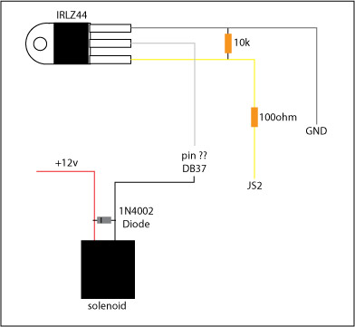
Js11 is for boost control in 3.2.1 and the diy kit didn't include the diode that goes between solenoid.
that's it.
I checked resistance on my circuit and the 10k resister is grounding out the signal.
Is that normal? Don't see any other way it could not ground it. But everything is not shorting
to anything else. What else to check?
Out: to solenoid is connecting.
ground: to js11 is getting 10k because of the resister so everything is flowing good, no breaks.
The transistor isn't grounded out to anything either.
Nothing is touching anything else. Very frustrating.
I fallowed these directions.
Js11 is for boost control in 3.2.1 and the diy kit didn't include the diode that goes between solenoid.
that's it.
Last edited by Mr.Pibb; Apr 17, 2012 at 04:17 PM.
Reply
0
0

Thread
Thread Starter
Forum
Replies
Last Post
StratoBlue1109
Miata parts for sale/trade
21
Sep 30, 2018 01:09 PM
Frank_and_Beans
Supercharger Discussion
13
Sep 12, 2016 08:17 PM


