First start after rebuild woes - sync loss 31 and 32
#1
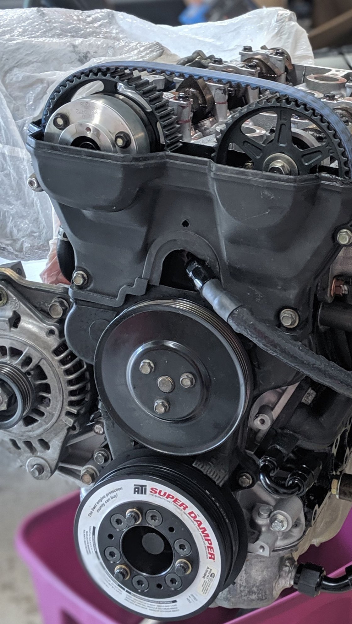
After half a year of getting dicked around by parts suppliers and machine shops, I was able to shove my rebuilt 01 VVT motor into my NA6 and attempt to start it for the first time last night. To my dismay the motor stumbled, coughed, and generally ran like ***... well if you can call it "running". A little back story, Last year i pulled out a 1.6 motor that had a head gasket leak and replaced it with a part-out 01 VVT motor, swapped out my MSPNP2 for a MS3 Basic and enjoyed some of the summer with the car, while the motor ran pretty good it did turn out to have some lazy rings / valve seals and would consume copious amounts of oil on any longer drives. This lead me down the path of a rebuild, and the "if im in there, i may as well" bug bit. Motor is as follows:
01 VVT
+1 Manley valves
OE valve seals
9:1 SuperTech pistons / Wiesco rings
Manley rods
King bearings
Boundry 72psi VVT pump
ATI damper
01 stock coils
Square top
FlowForce 640cc injectors
Kraken Manifold / 3" turboback
Batch spark
Sequential fuel ( this was done last year when the VVT motor went in and ran really well)
I was greatly hoping for the motor to go into the car, change the ReqFuel and Ign dead times to the spec provided by FlowForce and it would run, for the most part.
The tune I had from Rev changed a little bit as there is also a turbo in the mix now i based the Ign/Afr/VE tables off of the basemaps for an 01+ from trubokitty. Everything else remains largely the same.
As stated above, the engine struggles to start, and when running it sounds like its missing, cylinder 3 and 4 are much colder to the touch than 1 and 2, based on my hand thermometer touching the exhaust manifold runners.
The sync loss counter climbs considerable as the engine attempts to run and throws Loss Sync reason 31 and 32 which are:
What i've tried:
Attached are the tune file, composite log from cranking, a short running log that shows the sync errors and a youtube video showing it running. Im at a loss as to the problem and what next steps I should take to resolve them.
01 VVT
+1 Manley valves
OE valve seals
9:1 SuperTech pistons / Wiesco rings
Manley rods
King bearings
Boundry 72psi VVT pump
ATI damper
01 stock coils
Square top
FlowForce 640cc injectors
Kraken Manifold / 3" turboback
Batch spark
Sequential fuel ( this was done last year when the VVT motor went in and ran really well)
I was greatly hoping for the motor to go into the car, change the ReqFuel and Ign dead times to the spec provided by FlowForce and it would run, for the most part.
The tune I had from Rev changed a little bit as there is also a turbo in the mix now i based the Ign/Afr/VE tables off of the basemaps for an 01+ from trubokitty. Everything else remains largely the same.
As stated above, the engine struggles to start, and when running it sounds like its missing, cylinder 3 and 4 are much colder to the touch than 1 and 2, based on my hand thermometer touching the exhaust manifold runners.
The sync loss counter climbs considerable as the engine attempts to run and throws Loss Sync reason 31 and 32 which are:
- 31 = Miata 99-00 - 2 cams not seen
- 32 = Miata 99-00 - 0 cams seen
What i've tried:
- Checked spark plugs and gap
- also tried known working plugs from last years motor
- Made sure coils are seated and connectors are seated
- Checked compression, mind you; relatively cold engine, rings not seated
- Cyl 1: 130
- Cyl 2: 128
- Cyl 3: 134
- Cyl 4: 134
- Checked ECU grounds
- Checked Chassis/Motor ground
- Checked crank angle sensor spacing to trigger wheel - credit card gap
- Checked trigger wheel orientation - 4 tooth wheel
- at TDC bottom tooth is just past 6 o'clock
Attached are the tune file, composite log from cranking, a short running log that shows the sync errors and a youtube video showing it running. Im at a loss as to the problem and what next steps I should take to resolve them.
#3

#7
Spent some time last evening going over everything again and used Tuner Studio test modes to validate injectors and coils are firing. I also went to validate the air gap on the crank trigger wheel and noticed the crank position sensor had a big slice through it from a gear tooth. After some digging online my buddy as able to locate a bench procedure with a DMM to verify if the sensor was good/bad, here's the spec for posterity:
The sensor has a resistance of 455Ohms and read 0v when cranking by probing pins 1 and 2 listed above, this means the sensor is bad, obviously from the damage it had from then trigger wheel tooth.
I bought a new crank position sensor and cam position sensor, upon installing the crank position sensor I wanted to check the tooth height on the trigger wheel that came with my damper from Fab9, 3 of the 4 teeth measured ~2.35mm and the 4th tooth measured ~2.75mm, I obviously set the air gap on one of the shorter teeth and the longer tooth cut the sensor open on cranking. I measured the OEM trigger wheel teeth and all of them are ~2.0mm. Damnit.
I set the new air gap on the tallest tooth, and the car fired up immediately, no more stumbling. However there is a massive oscillation while attempting to idle, and while it does idle it, it is still losing sync with the reason codes of 31 and 32, same as my original findings.
I'm wondering if the .4mm tooth height discrepancy is causing the loss of sync which makes the injection and ignition events to not happen. I'm going to attempt to file down the long tooth to meet the same height as the other 3 teeth before pulling the damper and getting a new trigger wheel.
CKP Sensor on the crank
This actual crank sensor was added for OBD2 misfire monitoring. It is a magnetic pickup that produces an A/C voltage signal when engine rotation occurs. CKP wheel at crank has teeth that pass by CKP sensor during engine rotation producing an a/c voltage (NE) signal. Signal is used by PCM to determine engine speed by monitoring position of #1 CYL.
Signal is also used for fuel injection timing and is primary input for ignition control. Signal is also used for severe misfires that can cause CAT damage to occur. Misfires that increase emissions are detected when 1000 crankshaft revolutions exceed threshold. Misfires that can damage catalyst are detected when 200 crankshaft revolutions exceed threshold. CKP signal is very accurate and is not effected by loose timing belt.
I have found that the tooth that indicates CYL1 is actually 10degBTDC making it possible to set base timing using a scope.
Best Test Location
grey connector at timing cover, you may have to remove intake tube to gain access
Component Location
Crankshaft pulley
Connector
Harness side, backprobing, tab in the top center
[ 1 2 3 ]
1=CKP Signal (-)
2=CKP Signal (+)
3=Ground
Testing
You can use a DMM set to AC voltage and see what you get while cranking the engine. Connect the leads to pin 1 and 2. If 0 VAC suspect bad sensor.
Resistance across CKP+ and CKP- shoudl be about 500Ohms to 600Ohms
I bought a new crank position sensor and cam position sensor, upon installing the crank position sensor I wanted to check the tooth height on the trigger wheel that came with my damper from Fab9, 3 of the 4 teeth measured ~2.35mm and the 4th tooth measured ~2.75mm, I obviously set the air gap on one of the shorter teeth and the longer tooth cut the sensor open on cranking. I measured the OEM trigger wheel teeth and all of them are ~2.0mm. Damnit.
I set the new air gap on the tallest tooth, and the car fired up immediately, no more stumbling. However there is a massive oscillation while attempting to idle, and while it does idle it, it is still losing sync with the reason codes of 31 and 32, same as my original findings.
I'm wondering if the .4mm tooth height discrepancy is causing the loss of sync which makes the injection and ignition events to not happen. I'm going to attempt to file down the long tooth to meet the same height as the other 3 teeth before pulling the damper and getting a new trigger wheel.
#9
Here's the link to the resource I found
https://sites.google.com/site/miatad...ensor-on-crank
#10
Elite Member

iTrader: (10)
Join Date: Jun 2006
Location: Athens, Greece
Posts: 5,978
Total Cats: 356
That's for the 96-97 NA which only has a VR sensor on the crank for misfire detection (and still has a CAS sensor on the head for RPM and timing). You are getting a normal crank and cam signal in your log. You have a phasing issue, this means the crank/cam correlation is not correct, as if the timing is bad. In the NB engine, it is notoriously easy (and common) to put the crank trigger wheel backwards, resulting in this problem.
#11
That's for the 96-97 NA which only has a VR sensor on the crank for misfire detection (and still has a CAS sensor on the head for RPM and timing). You are getting a normal crank and cam signal in your log. You have a phasing issue, this means the crank/cam correlation is not correct, as if the timing is bad. In the NB engine, it is notoriously easy (and common) to put the crank trigger wheel backwards, resulting in this problem.
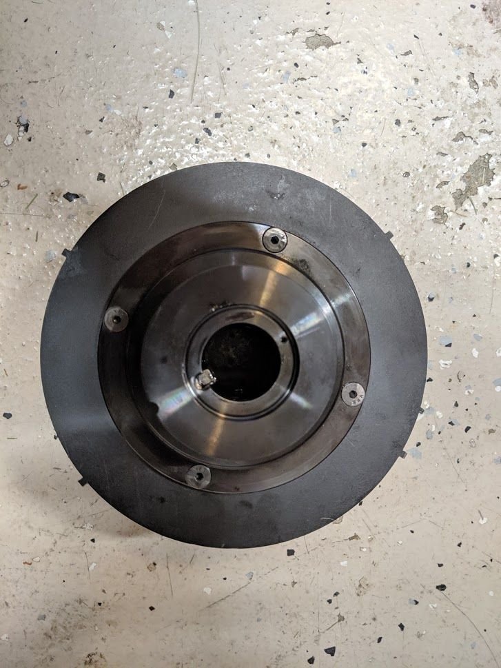
I wanted to dig more into why the crank position sensor got destroyed by timing wheel tooth contact, as I had previously set the air gap to a credit card thickness before first crank. I ended up setting the air gap off a tooth that was much closer to the crank sensor than the other to get the car started again. It fired up immediately and once running I noticed the trigger wheel having a wobble. I took a piece of coat hanger to use as a makeshift dial indicator to try to verify how much wobble is on the trigger wheel.
So.. uhh... that doesnt look right... It would seem to me that the ECU is missing trigger events because of the wobble of the trigger wheel and how far away some of the teeth are from the sensor. I had to pull the damper, which on the car is not very fun. with the damper off the car, it was immediately noticeable there is something wrong with the trigger wheel.

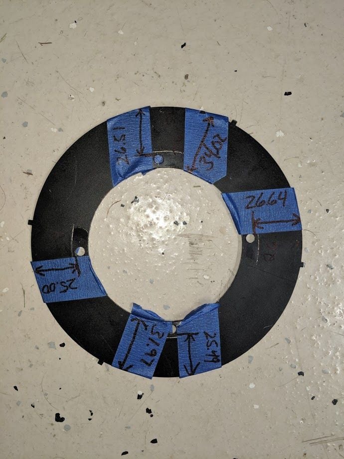
I took some measurements to see how far off it actually was. Since the center hole is slightly larger than the shelf on the damper the trigger wheel sits on for wiggle room, I measured from the edge of the bolt holes, as well as from the ID to the OD of the largest and smallest sides of the wheel.

so one side of the wheel would be ~2.05mm closer to the sensor then the other. I ordered a 36-2 wheel from FM to replace the 4 tooth I got from Fab9 when I bought the damper, and also waiting for a new woodruff because I sheared the one installed when pulling the damper.
#15
Follow up post time:
Changing out the trigger wheel solved the sync loss issue and the engine now starts and idles like it should. The sync loss was 100% caused by shitty trigger wheel because of the center bore and mounting holes being offset to the OD of the wheel, this made the teeth on the wheel too far away from the sensor to get an event.
Changing out the trigger wheel solved the sync loss issue and the engine now starts and idles like it should. The sync loss was 100% caused by shitty trigger wheel because of the center bore and mounting holes being offset to the OD of the wheel, this made the teeth on the wheel too far away from the sensor to get an event.
Thread
Thread Starter
Forum
Replies
Last Post
Stockish
Engine Performance
8
10-17-2016 09:47 AM


