
Fuel pump circuit


Thread Starter
Elite Member
iTrader: (16)
Joined: Oct 2006
Posts: 1,656
Total Cats: 526
From: Las Cruces, NM
I built and installed a DIYPNP for my friend's 1.6 '90. The fuel pump doesn't start. I built the DIYPNP as instructed:
To successfully gain control over the fuel pump circuit, first you need to be sure you remove the "ST SIG" fuse for the 90 to 93 model Miata. Jumper from "Fuel Pump" on the edge of the main board to "IN" on the high side driver circuit. Jumper from "OUT" of the high side driver circuit to terminal 1C on the connectorboard.
This failed. So, I jumpered FP to gnd in the diagnostic port and the car starts and runs. Do I have to make the circuit for the FP like the vtec circuit in the proto area to eliminate the jumper bandaid?
Reply
 0
0

0


Do I have to make the circuit for the FP like the vtec circuit in the proto area to eliminate the jumper bandaid?
It's easier to send the fp ground to 2O and jump the connection to the FP relay through the AFM connector.
Reply
0
0
Thread Starter
Elite Member
iTrader: (16)
Joined: Oct 2006
Posts: 1,656
Total Cats: 526
From: Las Cruces, NM
Thanks Scott,
This ECU was purchased used. I'm just helping him to sort it out. It was partially assembled and I had to go over all the build steps to verify that it was assembled correctly and added what was necessary for his car. So from what I understand, I connect the fuel pump connection on the 1.5B mainboard to 2O
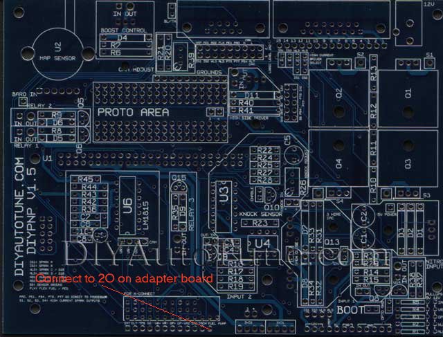
and jumper the AFM connecter like this:
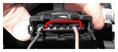
This ECU was purchased used. I'm just helping him to sort it out. It was partially assembled and I had to go over all the build steps to verify that it was assembled correctly and added what was necessary for his car. So from what I understand, I connect the fuel pump connection on the 1.5B mainboard to 2O
and jumper the AFM connecter like this:
Last edited by 99mx5; Jan 23, 2014 at 08:44 PM. Reason: More detail on build.
Reply
0
0
Thread Starter
Elite Member
iTrader: (16)
Joined: Oct 2006
Posts: 1,656
Total Cats: 526
From: Las Cruces, NM
We opened up the MS and found that there is no 2O on the adapter board. The connector for 2 only goes up to L.in any event, the factory harness only uses the connectors for 1 and 4. Any suggestions?
Reply
0
0

Thread
Thread Starter
Forum
Replies
Last Post


