
IAC doesn't work. what did i eff up?


Thread Starter
Newb
Joined: Jul 2011
Posts: 17
Total Cats: 0
90 miata, MS1, V3.0, hi res firmware, using the 90-93 MSPNP IAC settings.
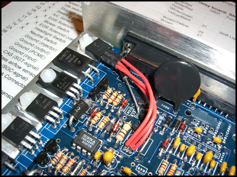
i bought the IAC mod kit from DIYautotune. kinda rushed through the install not paying enough attention. big suprise, the IAC didn't work. started looking for the issue, i am getting 12v at the white/red wire at the IAC, so that it good. the wire going from MS to the IAC is good. the TIP transistor is ran to Q4. the diode is running from the middle leg of the transistor to s13(IIRC) on the board, banded side towards the board. i went to double check the wiring and i noticed i had pin 1 and 3 on the TIP transistor reversed. i also forgot to pull resistor D8, but i actually caught that after the first time it wouldn't work, so it was just left in for the first few minutes.
i have plugged in another IAC and no change. if you hook power and ground to the IAC it moves all the way to the opposite side, so the valves are both good. so in short, what did i burn up on the megasquirt? i was planning on going to radioshack and trying to pick up a new transistor and diode and trying again. nothing "looks" burned on the board, and everything else still works fine.
Reply
 0
0

0
Supporting Vendor

Joined: Sep 2006
Posts: 2,332
Total Cats: 67
Can you get the idle LED to brighten and dim on the Stim with this?
Reply
0
0


Thread Starter
Newb
Joined: Jul 2011
Posts: 17
Total Cats: 0
just went out with a multimeter. full 12v at the red/white wire. there is .12v between the 2 IAC wires.
i do remember with the old transistor i actually had .9v at the blue and orange wire for some reason.
is there anywhere else i can run the IAC circuit beside Q4?
i do remember with the old transistor i actually had .9v at the blue and orange wire for some reason.
is there anywhere else i can run the IAC circuit beside Q4?
Reply
0
0
Supporting Vendor
Joined: Sep 2006
Posts: 2,332
Total Cats: 67
In that case, please test the signal on pin 1 and 2 of the TIP122 with your oscilloscope on the car.
Reply
0
0


Thread
Thread Starter
Forum
Replies
Last Post
Frank_and_Beans
Supercharger Discussion
13
Sep 12, 2016 08:17 PM


