Hydra to MS2v3
 07-03-2012, 10:47 PM
#1
Junior Member
Thread Starter
iTrader: (3)

Join Date: Apr 2010
Location: San Antonio, TX
Posts: 410
Total Cats: 1
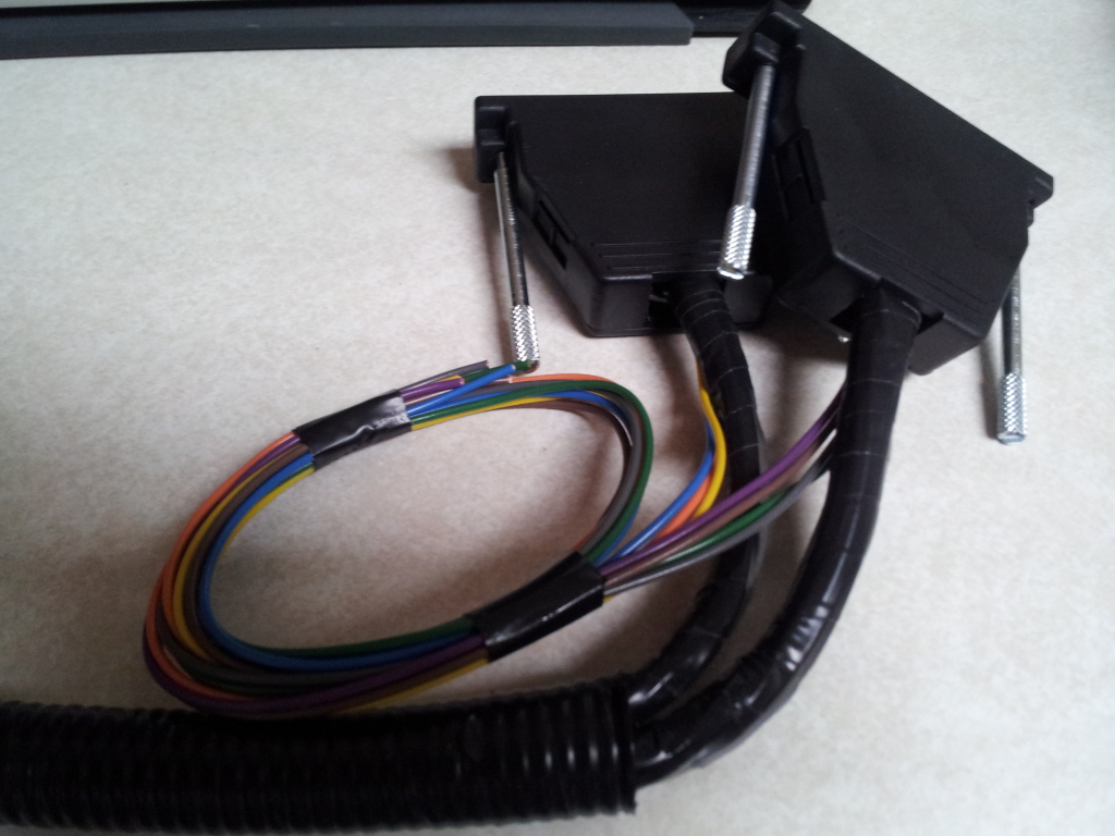
Sup guys, I'm in the process of switching out the Hydra 2.5 for my newly acquired MS2v3 and I'm figuring out the last steps of hooking up my LC-1 wideband and the GM Open Air IAT. I e-mailed Reverant but it's 5am in Greece sooooo I don't think he'll get back to me soon, hehe.
I have the Reverant MegaSquirt 2 V3 for my 2000 Miata, Innovative LC-1 wideband, and the GM Open Air IAT sensor.
What is the black wire on Pin 7 for? Does that just mean a common ground or is this pin specific to something else? I see it connecting for example to the other side of the wideband controller but I do not see a black wire from the harness.
Diagram: http://msextra.com/doc/general/pix/ms2v3-external.png
LC-1: Just to confirm, does the purple wire on the harness go to one of the analog outputs from the wideband controller? Is this the only connection between the two? I noticed a black wire between the harness and the controller but I do not see a black wire coming out from the controller like the purple one.
IAT: Does this wire into the stock location like the Hydra does (I'm assuming since the previous owner installed the Hydra) or does the orange wire from the harness wire up to the IAT?

Reply
 0
0

0
07-04-2012, 02:19 AM
#2
Tour de Franzia

iTrader: (6)
Join Date: Jun 2006
Location: Republic of Dallas
Posts: 29,085
Total Cats: 375
LC-1: Just to confirm, does the purple wire on the harness go to one of the analog outputs from the wideband controller? Is this the only connection between the two? I noticed a black wire between the harness and the controller but I do not see a black wire coming out from the controller like the purple one.
Reply
0
0
07-04-2012, 02:46 AM
#3
Elite Member
iTrader: (10)
Join Date: Jun 2006
Location: Athens, Greece
Posts: 5,977
Total Cats: 356
Ignore the wiring diagram you posted above. Here is the list of the free-hanging wires:
Yellow - Wideband input. Connect this to your wideband analog output
Grey - Switchable tables. Connect this to a ground (through an on/off
switch) to switch between VE/Ignition tables.
Brown - Launch control. Connect this to a ground (through an on/off switch)
to switch launch control on/off.
Violet (purple) - Boost control low/high. Connect this to a ground
through an on/off switch) to switch between low/high boost tables
Green - Boost control output. Connect this to a boost control valve. The other wire of the boost control valve needs to be connected to a switched and fused 12V source. A 5A fuse is recommended.
Orange - Free programmable output 1, low side. Can drive any load up to 0.5A.
Blue - Free programmable output 2, low side. Can drive any load up to 0.5A.
The Enhanced MS2 uses the stock IAT location.
Reply
0
0
 07-05-2012, 12:21 AM
#5
Junior Member
Thread Starter
iTrader: (3)
Join Date: Apr 2010
Location: San Antonio, TX
Posts: 410
Total Cats: 1
She started right up on the first try tonight. Wooo! I lost the nut that holds the ECU bracket to the car.  Will have to find something similar at hardware store tomorrow and then I can put everything back together. I also have to order new tires since I found one in the left rear tire a couple days ago. I can't wait to drive her! She starts up and idles soooooo much better than the Hydra that was in there before.
Thanks again!
Will have to find something similar at hardware store tomorrow and then I can put everything back together. I also have to order new tires since I found one in the left rear tire a couple days ago. I can't wait to drive her! She starts up and idles soooooo much better than the Hydra that was in there before.Thanks again!
Last edited by RavynX; 07-05-2012 at 12:33 AM.
Reply
0
0
07-05-2012, 10:05 AM
#7
Junior Member
Thread Starter
iTrader: (3)
Join Date: Apr 2010
Location: San Antonio, TX
Posts: 410
Total Cats: 1
I have a Hydra startup clip and last night's MS startup clip that I'll post to youtube later.
Reply
0
0

 07-05-2012, 11:02 AM
#12
Junior Member
Thread Starter
iTrader: (3)
Join Date: Apr 2010
Location: San Antonio, TX
Posts: 410
Total Cats: 1
lol, true. I'm just glad I didn't have a US 90-93 (edit: fixed) where I would have to remove the "ST SIGN" fuse to not damage the EMS. 
Man, the car purrrs so nicely now and it smells no where NEAR as rich as the Hydra did. I can't wait to see better MPG than 18-20.
Man, the car purrrs so nicely now and it smells no where NEAR as rich as the Hydra did. I can't wait to see better MPG than 18-20.
Reply
0
0
 90-93 1.6 US (94-97 1.6 EU as well)
07-06-2012, 11:39 AM
90-93 1.6 US (94-97 1.6 EU as well)
07-06-2012, 11:39 AM
#15
Junior Member
Thread Starter
iTrader: (3)
Join Date: Apr 2010
Location: San Antonio, TX
Posts: 410
Total Cats: 1
I couldn't get my Macbook to recognize the USB-to-Serial device I used on the Hydra. If I can't get my macbook to recognize the USB-to-Serial device I'll just have to run the software in the virtual machine running Windows 7 on the macbook.
I went for a test drive last night after inflating the tire since it held air for a while. Initial startup idled mid-14s. It drove around great for a couple of miles while the water temp warmed up. I parked and idled back at my house and it was idling in the upper 12s and the water temperature crept up to 220*F which was odd b/c it never got above 207*F on the Hydra setup at the current ambient temperatures of 85-90*F at night. I popped the hood and it looked like the driver's side fan was spinning slower than normal. Is there a setting for this in the software?
I went for a test drive last night after inflating the tire since it held air for a while. Initial startup idled mid-14s. It drove around great for a couple of miles while the water temp warmed up. I parked and idled back at my house and it was idling in the upper 12s and the water temperature crept up to 220*F which was odd b/c it never got above 207*F on the Hydra setup at the current ambient temperatures of 85-90*F at night. I popped the hood and it looked like the driver's side fan was spinning slower than normal. Is there a setting for this in the software?
Reply
0
0
07-06-2012, 11:46 AM
#16
Elite Member
iTrader: (10)
Join Date: Jun 2006
Location: Athens, Greece
Posts: 5,977
Total Cats: 356
There is no setting for fan speed - on the Miata, the speed is dictated purely by the voltage of the entire electrical system, since it only uses a relay for on/off activation. If the Hydra was overcharging the system, that would explain why the fan would ran faster with the Hydra.
Reply
0
0
07-10-2012, 10:11 AM
#19
Junior Member
Thread Starter
iTrader: (3)
Join Date: Apr 2010
Location: San Antonio, TX
Posts: 410
Total Cats: 1
Actually the water temperature I'm reading is a separate sender & gauge unit which sits on the back of the head next to the stock water temp gauge.
I didn't get much time last night to log anything and it was also raining but I did go for a test drive and tested the "Start Auto Tune" feature under VE Analyze Live! just to see what it did and it modified some of the cells but it could not idle and would stall the car; it also would be very lean (19-20 AFR) on cruise between 30-50 mph. I will see if I can do a data log tonight; gotta read up on this stuff and figure it out.
I didn't get much time last night to log anything and it was also raining but I did go for a test drive and tested the "Start Auto Tune" feature under VE Analyze Live! just to see what it did and it modified some of the cells but it could not idle and would stall the car; it also would be very lean (19-20 AFR) on cruise between 30-50 mph. I will see if I can do a data log tonight; gotta read up on this stuff and figure it out.
Reply
0
0
07-14-2012, 10:44 AM
#20
Junior Member
Thread Starter
iTrader: (3)
Join Date: Apr 2010
Location: San Antonio, TX
Posts: 410
Total Cats: 1
Found out two things yesterday. The coolant reservoir was empty and the level inside the radiator was about 1" below the top. I need to figure out where it's going...
For the AFR issue, I had remembered the instructions that one of the two analog outputs from the LC-1 wideband controller is set as Narrowband out of the box. I connector up to the gauge and used the LM Programmer software to switch it over to wideband and it's reading 'somewhat' correctly in TunerStudio now.
TunerStudio is reading about 0.5-1.0 higher than the wideband gauge on my center console gauge. From what I can remember all of the grounds for the controller and the two gauges are going to the same point. Is there anything else I need to check to get the two analog outputs closer in sync or is this the best it will do?
Reply
0
0


