WTF and WHY did I do my LC-1 like this????
 04-22-2009, 11:29 AM
#1
Slowest Progress Ever

Thread Starter
iTrader: (26)
Join Date: Oct 2007
Location: The coal ridden hills of Pennsylvania
Posts: 6,025
Total Cats: 304
So from a previous thread, https://www.miataturbo.net/forum/t34195/ I was trying to figure out why my car won't keep a tune for more than a week, and Hustler and maybe someone else said about resetting the LC-1. So I said "I never wired up my push button and my LED". So I decided I should probably do this, and I stuck my head under the dash, and WTF. I think I may have found the issue, and I am kicking myself in the *** for my stupidity. In fact, when I go to the NE Dyno meet, I better get my *** kicked for this.
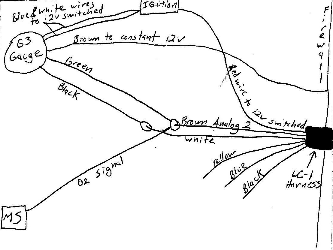
I wired my LC-1 like this:
According to the LC-1 instructions, I have the gauge wired correctly. As for the LC-1, the Yellow wire is not hooked to anything, cause I don't use analog output 1. The Black calibration wire isn't hooked up either, cause I'm not using the button and LED. The Blue wire isn't hooked up, and the White wire just goes to the gauges Black ground wire. So in other words, I have no grounds hooked up on my LC-1 harness, and no fuse between the Red 12v switched wire.
So I'm thinking, splice the White, Blue, and gauge's Black ground wires together...but should I run them to a ground in my parallel harness for the MS? After the grounds are hooked, then I should run the LED and push button between LC-1's Black calibration wire and the ground.
I have had it hooked up this way for over a year and a 1/2. I'm thinking the LC-1 was grounding at the sensor, so how would it stay calibrated? Am I going to need to recalibrate this thing after I hook it up the right way?
I deserve a group atomic wedgie for this....

Reply
 0
0

0
04-22-2009, 11:34 AM
#2
Sorry, but you really deserve this:
............................................______ __........................
....................................,.-��...................``~.,..................
.............................,.-�...................................�-.,............
.........................,/...............................................�:, ........
.....................,?........................... ...........................\,.....
.................../.................................................. .........,}....
................./.................................................. ....,:`^`..}....
.............../.................................................. .,:�........./.....
..............?.....__............................ .............:`.........../.....
............./__.(.....�~-,_..............................,:`........../........
.........../(_....�~,_........�~,_....................,:`..... ..._/...........
..........{.._$;_......�=,_.......�-,_.......,.-~-,},.~�;/....}...........
...........((.....*~_.......�=-._......�;,,./`..../�............../............
...,,,___.\`~,......�~.,....................`..... }............../.............
............(....`=-,,.......`........................(......;_,,-�...............
............/.`~,......`-...............................\....../\...................
.............\`~.*-,.....................................|,./.....\,__...........
,,_..........}.>-._\...................................|........... ...`=~-,....
.....`=~-,_\_......`\,.................................\... .....................
...................`=~-,,.\,...............................\............. ..........
................................`:,,.............. .............`\..............__..
.....................................`=-,...................,%`>--==``.......
........................................_\........ ..._,-%.......`\...............
...................................,<`.._|_,-&``................`\..............
I have no idea how your **** was even running, but you should definitely do a free air calibration once you fix it, and reset your outputs.
You're basically starting off like a new install, well, because you are. What you had isn't considered an install from the MS point of view, you basically just had a pretty gauge telling you about a noisy, uncalibrated sensor.
Glad you found the problem.
Do the newbs a favor and also put this link in the other thread if you haven't already.
Reply
0
0
04-22-2009, 11:35 AM
#3
Elite Member

Join Date: Mar 2008
Location: Enschede, NL
Posts: 2,053
Total Cats: 12
cause I don't use analog output 1
And fix your grounds. Ground the harness separately as discussed widely at the engine block near the TB.
Then recalibrate. This can be done with the probe still in the exhaust as long as you haven't driving your car for a month. This is actually something like a day but I don't remember.
Reply
0
0
 04-22-2009, 11:36 AM
#5
Boost Czar

iTrader: (62)
Join Date: May 2005
Location: Chantilly, VA
Posts: 79,501
Total Cats: 4,080
does the MS know youre outputting 0-5v 7.35-22.39:1 AFR????
Where is the white wire on the LC-1 grounded? Where is the blue?
I suggest removing the MS from the analog 2 (brown) and switching it tho analog 1 (yellow), then in logworks making sure it outputs 0-5v 10-20:1 AFR
Leave the Black wire disconnected, but make sure it will never touch a ground (tape it).
Reply
0
0
04-22-2009, 11:53 AM
#7
Slowest Progress Ever
Thread Starter
iTrader: (26)
Join Date: Oct 2007
Location: The coal ridden hills of Pennsylvania
Posts: 6,025
Total Cats: 304
So correct me if I'm wrong, cause I probably am...I should splice a 5amp minimum fuse on the 12V Red switch wire for the LC-1 harness. The Blue and the White LC-1 ground wires should go to the same grounding point, same for the gauge's Black wire. Where should that grounding point be? So I won't put the push button or the LED in, I will leave the Black LC-1 calibration wire disconnected. As for the signal wires, I should leave the gauge on Brown Analog 2? and run the MS on the Yellow Analog 1 wire? So once I hook everything back up, I disconnect my O2 sensor at the plug, unscrew it from the DP and do it like it's brand new, and this should recalibrate?
Reply
0
0
04-22-2009, 12:07 PM
#9
...and ground to where your ECU ground is, on your car I believe under or near throttle body.
I never push my button, have always done a free air cal. at the same time, but the LED is important, it indicates warmup and error codes.
Yep, sounds right. Just make sure the one you run to MS you set for 0-5v, 10-20 linear in LM Programmer after you do the free air.
It will do both a heater calibration and AFR cal at the same time, just like new. You disconnect the sensor from the Innovative controller (six pin D shaped push connector), supply power for 20 sec, reconnect, supply power for ~2min. During this time the LED will start flashing, first slowly, then faster, then go on solid with a 21.8 on the gauge. Sometimes they calibrate faster...
Reply
0
0
04-22-2009, 12:12 PM
#10
Newb

Join Date: Jan 2007
Posts: 18
Total Cats: 0
I'm adding my name to this thread, because I will be buying a LC-1 soon, & can use any install tips.
no intention of hijacking, but I like the G3 guage, too (looks like an analog). as I'm guessing the digital guages would always be flickering even distracting?
I was planning to mount the red recalibration button in the glovebox.
no intention of hijacking, but I like the G3 guage, too (looks like an analog). as I'm guessing the digital guages would always be flickering even distracting?
I was planning to mount the red recalibration button in the glovebox.
Reply
0
0
04-22-2009, 12:18 PM
#11
Slowest Progress Ever
Thread Starter
iTrader: (26)
Join Date: Oct 2007
Location: The coal ridden hills of Pennsylvania
Posts: 6,025
Total Cats: 304
Braineack comes through again with the greatest illustraion ever. GoSpeed, thanks for the long description. Very quick responses guys, filled with usefull information. I wonder how incorrect my tune will be after I get this all back together. I should be able to datalog and then VE analyze it, and it'll run like a brand new car. I feel like such a dumbass, I can fabricate ****, figure out how to use MT and everything else, but I can't wire my wideband up, and that's the first thing I ever did to the car. Thanks a million guys! I'm going to wrench on it tomorrow and then I'll repost my results.
Reply
0
0
04-22-2009, 12:19 PM
#12
Slowest Progress Ever
Thread Starter
iTrader: (26)
Join Date: Oct 2007
Location: The coal ridden hills of Pennsylvania
Posts: 6,025
Total Cats: 304
I love the G3 gauge, cause I hate watching digital numbers blink. Definately use this thread for an installation reference.
Reply
0
0
04-22-2009, 01:59 PM
#13
Slowest Progress Ever
Thread Starter
iTrader: (26)
Join Date: Oct 2007
Location: The coal ridden hills of Pennsylvania
Posts: 6,025
Total Cats: 304
So I got impatient and I decided to work on it NOW. So instead of having the MS's O2 signal on the brown wire with the gauge's green wire, I ran the gauge only to Brown Output 2 and the MS signal comes from Yellow Output 1. I soldiered the Blue, White, and gauge's Black wires together and was looking for a ground. There is a wire that my oil temp gauge uses that goes through the firewall and is grounded to the block. It is a 12 gauge wire, I'm going to use this for the LC-1 grounding point unless somebody tells me otherwise. So aside from attaching this ground, recalibrating, and changing some stuff in LM programmer...I should have it licked. I still feel like an asswipe, but thanks again guys!
Reply
0
0
04-23-2009, 10:23 AM
#14
Slowest Progress Ever
Thread Starter
iTrader: (26)
Join Date: Oct 2007
Location: The coal ridden hills of Pennsylvania
Posts: 6,025
Total Cats: 304
So I wired everything up as per Braineack's illustration. I didn't re-calibrate it yet. As for MS configurator, do I still keep it set to LC-1 Default?
Reply
0
0
04-23-2009, 11:02 AM
#16
Slowest Progress Ever
Thread Starter
iTrader: (26)
Join Date: Oct 2007
Location: The coal ridden hills of Pennsylvania
Posts: 6,025
Total Cats: 304
So I just went in the garage and set MS Configurator to "INNOVATE_0_5_LINEAR Innovate, PLX 0-5v 10-20:1 AFR". Then I went into LM Programmer and changed Analog Out 1 to 0-5v 10-20. I left Analog Out 2 at the default setting. I didn't recalibrate it yet, but I started the car anyway. The gauge in MT matched the dash gauge if not exact, it was pretty damn close. Before, the car would idle at like 12.5:1 ish on the gauge, and now it idles at 14:1, somewhere around there. I work 3rd, so I'm gonna make some mac and cheese and take a nap, then I guess I'll pull the sensor and recalibrate it. I should be able to take it for a rip and datalog it, then I'll post my datalogs and .msq around dinner time. Thanks again guys.
Reply
0
0
 04-23-2009, 07:46 PM
#20
Slowest Progress Ever
Thread Starter
iTrader: (26)
Join Date: Oct 2007
Location: The coal ridden hills of Pennsylvania
Posts: 6,025
Total Cats: 304
So here it is...
I recalibrated the LC-1 and then I started the car and left it warm up. Once it was at temp, I pulled my plastic cover off of the fuse panel so I could plug my OBD-II code scanner in to clear my codes. My parallel harness is stuffed up under the dash, and part of it sticks out near the fuse panel. I bumped the harness and the car's idle started to F up. So I grabbed the harness and wiggled it, and then the car ran fine. So apparently there is a loose wire somewhere, everything is soldered though, and heat shrink wrapped.
Anyway, I hook up the laptop and start to record a datalog. I take it up the street about 4 miles and pull over at this hotel parking lot. I made a few changes to richen it out in the 3400-4000 RPM range at 80-90 kPA. Then I hit record for another datalog and I drove the car for about 20 minutes. Here is my current .msq and datalog. Note that I did not make any changes to this .msq yet. Please give opinions on my AFR target table, and my EGO settings.current.msq
lc1redone.xls
Reply
0
0


