MS1 random cut out while cruising
 11-19-2013, 02:59 PM
#1

Afternoon folks, I've been having a bit of a problem that I believe is Megasquirt related. While cruising, it often has a misfire that jerks the car, which is incredibly annoying. It seems to be accompanied with a massive RPM spike and the wideband reads a lean spike, also. Here's the specs of the car:
'96 Miata
MS1 3.0 board
T25 running 8 PSI
I've wired in the .1uf capacitor, and think my CAS is good, but I've heard that the CAS can have interference with other high voltage wires? Also, either I'm paranoid or I notice it more often, but it seems to get worse when I have a passenger in the car (MS is behind the passenger seat) or when it rains.
The reason that I suspect it is the Megasquirt is because I've had these symptoms with two different engines.
I've attached a log file with a few of the events. The first time I hit the spacebar in the log I believe was a fluke, but the second two times were definitely misfires. The last one probably being the best representation.

Reply
 0
0

0
11-19-2013, 03:09 PM
#2
Elite Member
iTrader: (2)

Join Date: May 2007
Location: Cromwell, Connecticut
Posts: 2,605
Total Cats: 16
Subscribed. I have looked into this issue before with not real findings. It happens on highway cruise to me quite frequently. Does not happen on the stock ecu. I've played with plugs, coils , grounding , capacitor, etc with no luck. Finally just learned to live with it. I did buy another CAS to try next spring though.
Reply
0
0
 11-28-2013, 08:28 PM
#7
Considering going to a crank trigger wheel setup. Looks like Joe Perez has used it to help get rid of his 'misfire' with good success.
https://www.miataturbo.net/megasquir...ss-last-20241/
I understand that I should need a trigger wheel : 2000 Mazda Protege Parts - Online Mazda Parts
and a crank angle sensor from an NB.
Still a bit unsure on what all is needed to take the cam angle sensor completely out of the equation, but still searching.
Reply
0
0
12-10-2013, 03:12 PM
#9

You need to make another optoisolator circuit for the 2nd input on the cas. Info is in here:
https://www.miataturbo.net/megasquir...tor-ms2-71250/
I haven't had a single dropout in the past year since doing this mod.
https://www.miataturbo.net/megasquir...tor-ms2-71250/
I haven't had a single dropout in the past year since doing this mod.
Reply
0
0
12-10-2013, 03:33 PM
#10
Is this the diagram you used to wire yours?
https://www.miataturbo.net/attachmen...-dscf6117g-jpg
Also, with MS1, how would I know I'm getting sync loss?
Also, after looking at a few logs Ive noticed that the cut out is not always accompanied by an rpm spike or drop. Could this be sync loss?
https://www.miataturbo.net/attachmen...-dscf6117g-jpg
Also, with MS1, how would I know I'm getting sync loss?
Also, after looking at a few logs Ive noticed that the cut out is not always accompanied by an rpm spike or drop. Could this be sync loss?
Reply
0
0
12-10-2013, 03:40 PM
#11
Is this the diagram you used to wire yours?
https://www.miataturbo.net/attachmen...-dscf6117g-jpg
Also, with MS1, how would I know I'm getting sync loss?
Also, after looking at a few logs Ive noticed that the cut out is not always accompanied by an rpm spike or drop. Could this be sync loss?
https://www.miataturbo.net/attachmen...-dscf6117g-jpg
Also, with MS1, how would I know I'm getting sync loss?
Also, after looking at a few logs Ive noticed that the cut out is not always accompanied by an rpm spike or drop. Could this be sync loss?
Reply
0
0
12-10-2013, 03:56 PM
#13
Like this https://www.miataturbo.net/attachmen...dcas_input-gif But Pin 2 comes in from the IAC1A on the harness If you set your megasquirt up like 99% of the people on here. The output goes to JS10 on MS2 I Dont recall what pin it was on MS1 but its the pin the the .1uf capacitor goes to. EDIT: It appears to be JS8 on MS1.
Reply
0
0
12-10-2013, 05:29 PM
#15
Like this https://www.miataturbo.net/attachmen...dcas_input-gif But Pin 2 comes in from the IAC1A on the harness If you set your megasquirt up like 99% of the people on here. The output goes to JS10 on MS2 I Dont recall what pin it was on MS1 but its the pin the the .1uf capacitor goes to. EDIT: It appears to be JS8 on MS1.
Reply
0
0
12-10-2013, 05:44 PM
#16
Elite Member
iTrader: (2)
Join Date: May 2007
Location: Cromwell, Connecticut
Posts: 2,605
Total Cats: 16
Proof I am a slacker...
https://www.miataturbo.net/megasquir...r-input-70794/
(I did actually try joes input at one point but the car didn't crank. I probably screwed up the circuit so I just said screw it and scrapped that idea)
I should build in the opto circuit this winter.
https://www.miataturbo.net/megasquir...r-input-70794/
(I did actually try joes input at one point but the car didn't crank. I probably screwed up the circuit so I just said screw it and scrapped that idea)
I should build in the opto circuit this winter.
Reply
0
0
 12-10-2013, 10:26 PM
#19
Junior Member

Join Date: Dec 2012
Posts: 105
Total Cats: 8
I, too, have the same issue.
MS1 v3 DIY built myself following the original thread.
I am getting dropouts around 3.5k RPM, so basically highway cruising.
I was able to follow the instructions pretty well to build the MS board as the picture tutorial was great. I tried to read the schematic but I am not 100% sure as I do not know symbols for everything. I used my mad MSPaint skills to add on to DIY's mod photo to show how I would solder in this 2nd opto circuit.
Can anyone confirm that this is correct?
Reply
0
0
12-11-2013, 12:57 AM
#20
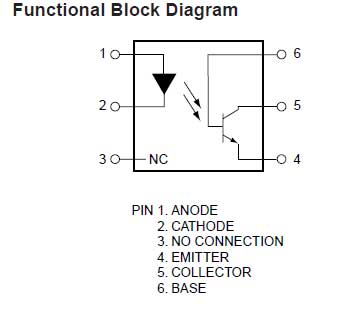
yea the 4n25 opto like This
Pro tip: apparently the dot on the top of the opto designates the #1 pin
Edit: kero that looks right to me, but my opinion is incredibly uninformed. Maybe someone with better knowledge than I can chime in
Last edited by mellowout; 12-11-2013 at 01:09 AM.
Reply
0
0


