MEGAsquirt A place to collectively sort out this megasquirt gizmo

MS3X Diode Wiring

Thread Tools
 
Search this Thread
 
Old 08-23-2015, 06:30 PM
  #1  
Junior Member
Thread Starter
iTrader: (1)
 
wred's Avatar
 
Join Date: Nov 2013
Posts: 71
Total Cats: 8
Default MS3X Diode Wiring

I'm stuck and need 2 things clarified about Part 3 of Frank's MS3/MS3X guide:

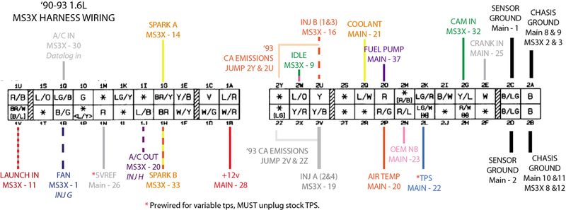
1. What pin is the a/c fan output on the MS3X? It's omitted on Frank's guide:
"Install a 1N4001 with the banded side to 12V (W/R wire in the ecu connector) and the other side to the a/c fan output of the MS3X (pin )."


2. Frank's guide says to connect 3 pins from the MS3X to the same 12v white/red wire in the ecu connector, BUT these same 3 pins also have OTHER locations shown in schematic above. For example, if you follow Frank's instructions you'd end up connecting MS3X pin 9 to the L/O ecu wire AND the 12v W/R wire. Do BOTH of these wires connect to the same side of the diode (the banded side)? Or does the L/O wire go straight to the PCB?

THIS?


OR THIS?
Attached Thumbnails MS3X Diode Wiring-80-s7ec1qnkfiotav_lhzxqapvvrw6oy_xkxhixgheu1oe_w1440_h810_no_jpeg_21302583fc0866628521c1e91ca87d.jpg  

Last edited by wred; 08-24-2015 at 07:55 AM.
wred is offline  
Old 08-23-2015, 06:44 PM
  #2  
Junior Member
Thread Starter
iTrader: (1)
 
wred's Avatar
 
Join Date: Nov 2013
Posts: 71
Total Cats: 8
Default

Uh I just thought about it. Wiring it up like the first picture wouldn't make any sense, haha. So it should be the bottom.

Just want to confirm though that each of these 3 pins do, in fact, go to 2 places, correct?
wred is offline  
Old 08-23-2015, 07:35 PM
  #3  
SADFab Destructive Testing Engineer
iTrader: (5)
 
aidandj's Avatar
 
Join Date: Apr 2014
Location: Beaverton, USA
Posts: 18,642
Total Cats: 1,866
Default

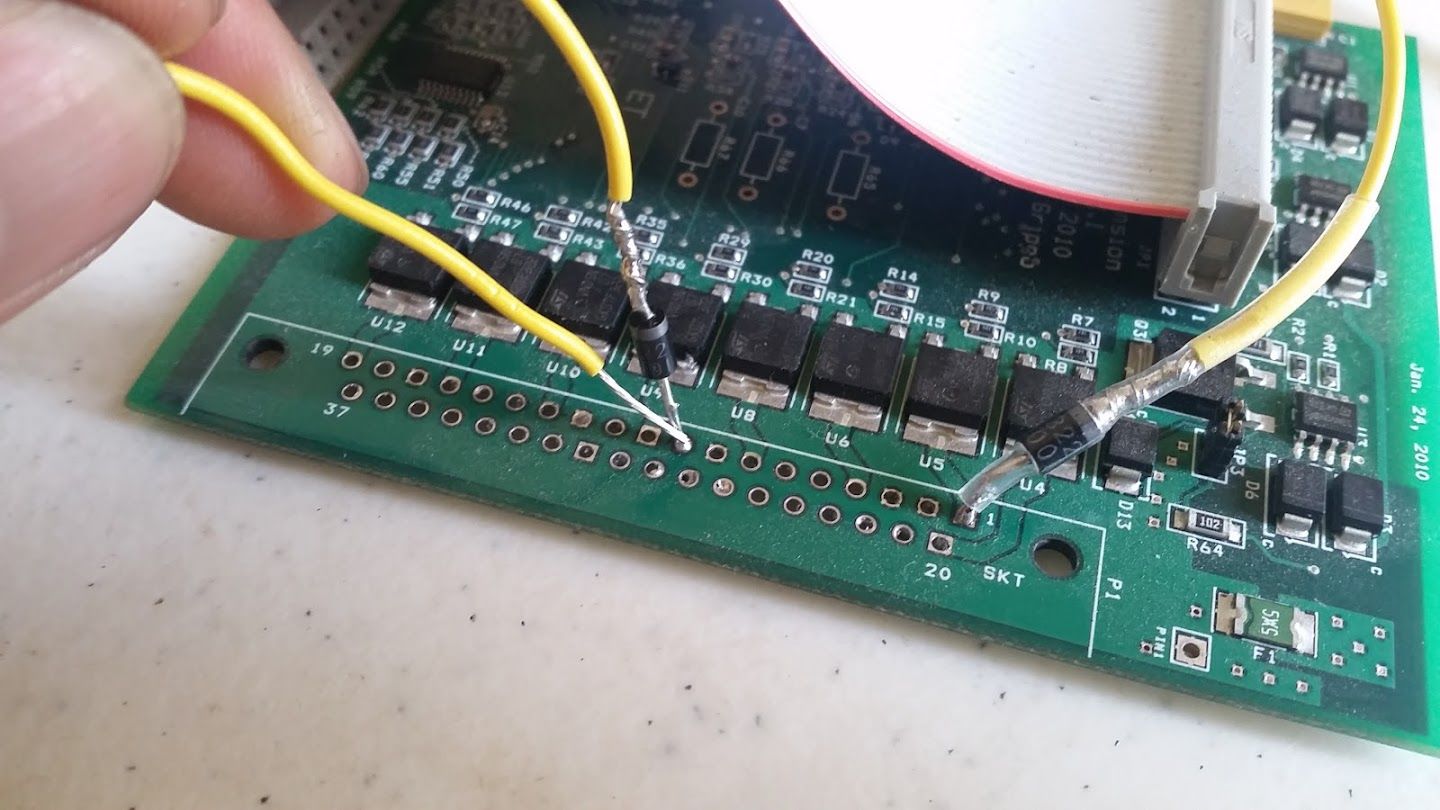
Your diode wiring is wrong. It should basically be a wire from the PCB to the output, and then T in a diode to 12v. Putting the diode how you have it will not allow the output to function.
aidandj is offline  
Old 08-23-2015, 07:35 PM
  #4  
SADFab Destructive Testing Engineer
iTrader: (5)
 
aidandj's Avatar
 
Join Date: Apr 2014
Location: Beaverton, USA
Posts: 18,642
Total Cats: 1,866
Default

Also, post he year of your car. Can't tell you where the AC fan output is if I don't k ow what year your car is.
<br />Looked at the diagram closer and I see its a 90-93.
<br />Here: http://www.miata.net/garage/ECU_Pin-Out.png
aidandj is offline  
Old 08-23-2015, 08:09 PM
  #5  
Ben
Supporting Vendor
iTrader: (33)
 
Ben's Avatar
 
Join Date: Jul 2006
Location: atlanta-ish
Posts: 12,659
Total Cats: 134
Default

<p>I don't see the need to add these diodes.&nbsp; The output circuits have flyback protection already.</p><p>But if you are going to do it, it's not right in your pictures.&nbsp; The non banded end would &quot;T&quot; into the output pin, banded end to switched 12V.</p>
__________________
Chief of Floor Sweeping, DIYAutoTune.com & AMP EFI
Crew Chief, Car Owner & Least Valuable Driver, HongNorrthRacing

91 Turbo | 10AE Turbo | 01 Track Rat | #323 Mazda Champcar

Originally Posted by concealer404
Buy an MSPNP Pro, you'll feel better.
Ben is offline  
Old 08-23-2015, 08:13 PM
  #6  
Boost Czar
iTrader: (62)
 
Braineack's Avatar
 
Join Date: May 2005
Location: Chantilly, VA
Posts: 79,493
Total Cats: 4,080
Default MS3X Diode Wiring

You don't need diodes. You just need to run 1 wire from s12 to the expander.
Braineack is offline  
Old 08-23-2015, 08:15 PM
  #7  
SADFab Destructive Testing Engineer
iTrader: (5)
 
aidandj's Avatar
 
Join Date: Apr 2014
Location: Beaverton, USA
Posts: 18,642
Total Cats: 1,866
Default

Unless the ms3x has changed then y8s had some old threads about higher current outputs (VVT, boost?) Needing it. Brain, you have old threads about needing it on the idle valve to put the duty cycle in the correct range.
aidandj is offline  
Old 08-23-2015, 08:22 PM
  #8  
Boost Czar
iTrader: (62)
 
Braineack's Avatar
 
Join Date: May 2005
Location: Chantilly, VA
Posts: 79,493
Total Cats: 4,080
Default

MS3XV30_Hardware-1.4 page 221

you dont need to add diodes, you just need to make the ones on the board go to 12v.
Braineack is offline  
Old 08-23-2015, 08:24 PM
  #9  
SADFab Destructive Testing Engineer
iTrader: (5)
 
aidandj's Avatar
 
Join Date: Apr 2014
Location: Beaverton, USA
Posts: 18,642
Total Cats: 1,866
Default

https://www.miataturbo.net/megasquir...-diodes-75851/
aidandj is offline  
Old 08-23-2015, 08:30 PM
  #10  
Boost Czar
iTrader: (62)
 
Braineack's Avatar
 
Join Date: May 2005
Location: Chantilly, VA
Posts: 79,493
Total Cats: 4,080
Default

i just posted the ******* manual. read it.
Braineack is offline  
Old 08-23-2015, 08:42 PM
  #11  
SADFab Destructive Testing Engineer
iTrader: (5)
 
aidandj's Avatar
 
Join Date: Apr 2014
Location: Beaverton, USA
Posts: 18,642
Total Cats: 1,866
Default

I have. I was just reading some old posts by y8s on msextra about those diodes not being able to handle it. He had a diode fall off because of overheating because the flyback current got dumped onto the PCB instead of externally where it should be.
aidandj is offline  
Old 08-23-2015, 08:49 PM
  #12  
Boost Czar
iTrader: (62)
 
Braineack's Avatar
 
Join Date: May 2005
Location: Chantilly, VA
Posts: 79,493
Total Cats: 4,080
Default

yeah, that was unmodded.

just run the single wire as the docs show. thats ultimately what y8s did to solve the issue.
Braineack is offline  
Old 08-24-2015, 07:58 AM
  #13  
Junior Member
Thread Starter
iTrader: (1)
 
wred's Avatar
 
Join Date: Nov 2013
Posts: 71
Total Cats: 8
Default

Ok, thanks for clearing that up, guys. No diodes, then. What about the A/C fan output? Anyone know what pin that is supposed to be on the MS3X?

Also, if I don't need the diodes, do I still need to connect pins 1, 9, and the mystery pin for the A/C fan output to the 12v W/R wire? I.e. do these three pins each need 2 wires connected to them? For instance do the L/O ecu wire AND the 12v W/R wire both connect to pin 9 of the MS3X?

Last edited by wred; 08-24-2015 at 08:19 AM.
wred is offline  
Old 08-24-2015, 08:21 AM
  #14  
SADFab Destructive Testing Engineer
iTrader: (5)
 
aidandj's Avatar
 
Join Date: Apr 2014
Location: Beaverton, USA
Posts: 18,642
Total Cats: 1,866
Default

No. You never connected them both. He said to connect a diode between them.
<br />AC out is any output. I think I used nitrous 2? Or an injector output.
aidandj is offline  
Old 08-24-2015, 08:48 AM
  #15  
Boost Czar
iTrader: (62)
 
Braineack's Avatar
 
Join Date: May 2005
Location: Chantilly, VA
Posts: 79,493
Total Cats: 4,080
Default

you dont need to add ANY diodes for a typical MS3x build.

if you are, you're doing it wrong.

fan output can be anything: I use a spare INJ drivers, some people the spare medium current outputs like nitrous or vvt.


the diagram you posted is mine. and I can't find references to the "1N4001" for a/c fan on Frank's guide--only the idle and that's unnecessary if you mod the expander like what's officially documented.

the a/c fan doesn't have its own relay on a 90-93. if you turn the compressor on, the a/c fan and main fan run.

Last edited by Braineack; 08-24-2015 at 08:59 AM.
Braineack is offline  
Old 08-24-2015, 09:02 AM
  #16  
Senior Member
iTrader: (1)
 
acedeuce802's Avatar
 
Join Date: Dec 2010
Location: Farmington Hills, MI
Posts: 1,218
Total Cats: 175
Default

The WestfieldMX5 guides recommend using diodes for A/C, Fan, VICS, and Idle.
acedeuce802 is offline  
Old 08-24-2015, 09:06 AM
  #17  
Boost Czar
iTrader: (62)
 
Braineack's Avatar
 
Join Date: May 2005
Location: Chantilly, VA
Posts: 79,493
Total Cats: 4,080
Default

That's because Frank apparently didn't get the memo...

dont install diodes--install the wire to 12v and forget all about diodes.

Then just worry about running 40-odd wires inside a case with no room for 40-odd wires...


how many times do i have to say it? YOU DO NOT NEED TO INSTALL DIODES.

a ms3x unit needs (3-4) modifications in order to make it run any 90-05 miata.

1. The (2) VR input jumpers and pull-up using the 1K to r13 and r45.
2. Pull-up from s12c to JS9
3. Flyback modification wire to s12 for the expander.
4. *OPTIONAL* 1K Pull-up to 5v for NB alternator.

that's it. Then it's all harness assembly. The only difference between any MS3x I build is step 4 depending if I'm building it for an NB or not.
Braineack is offline  
Old 08-24-2015, 10:49 AM
  #18  
SADFab Destructive Testing Engineer
iTrader: (5)
 
aidandj's Avatar
 
Join Date: Apr 2014
Location: Beaverton, USA
Posts: 18,642
Total Cats: 1,866
Default

<p>So you're saying we don't need diodes for an MS3x build?</p><p>&nbsp;</p><p>&nbsp;</p><p>&nbsp;</p><p>&nbsp;</p><p>&nbsp;</p><p>&nbsp;</p><p>&nbsp;</p><p>&nbsp;</p><p>&nbsp;</p><p>&nbsp;</p><p>&nbsp;</p><p></p>
aidandj is offline  
Old 08-24-2015, 12:06 PM
  #19  
Boost Czar
iTrader: (62)
 
Braineack's Avatar
 
Join Date: May 2005
Location: Chantilly, VA
Posts: 79,493
Total Cats: 4,080
Default

no. take a handful and shove them up your ***!
Braineack is offline  
Old 08-24-2015, 12:09 PM
  #20  
SADFab Destructive Testing Engineer
iTrader: (5)
 
aidandj's Avatar
 
Join Date: Apr 2014
Location: Beaverton, USA
Posts: 18,642
Total Cats: 1,866
Default

<p><img alt="love" src="https://www.miataturbo.net/images/smilies/love.gif" style="height:32px; width:40px" title="love" /></p>
aidandj is offline  


Quick Reply: MS3X Diode Wiring


All times are GMT -4. The time now is 08:34 AM.