Using Alt control circuit on 1.6 VVT swap - wiring?
 06-19-2013, 02:55 AM
#1
Elite Member
Thread Starter

Join Date: Mar 2006
Location: Schwarzenberg, Germany
Posts: 1,554
Total Cats: 101
Hi guys,
I have a thread going on with my 1996 (90bhp) Euro 1.6 to VVT swap attempt.
Here: https://www.miataturbo.net/engine-pe...uro-car-72134/
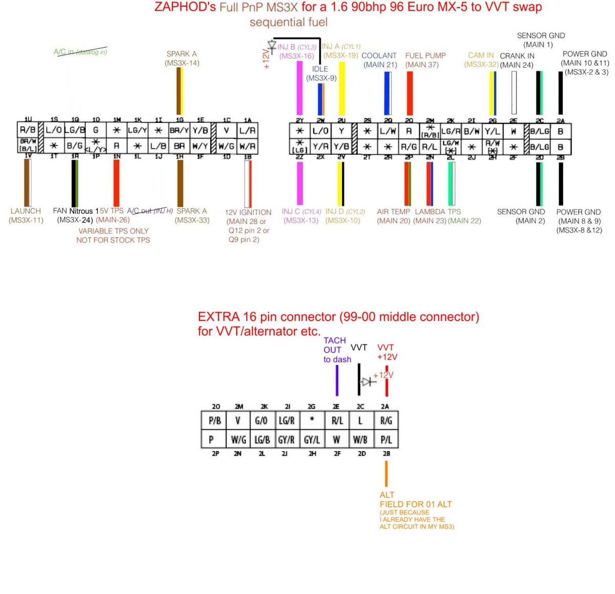
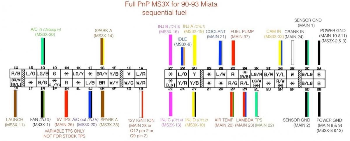
Now I re-wired my MS3 + MS3x (DIY Frank's PNP style) from my 99-00 car for the 1996 wiring (which is nearly identical to the 1990-93 wiring, apart from already being sequential injection) according to this schematic:
Now I need some help about the alternator wiring.
I do have in fact an spare 1.8 94-97 alternator here - just in case.
But as I do already have a working alternator circuit inside my MS3, I would like to check the possibilities to use it, but as I am no electronic expert I need some help.
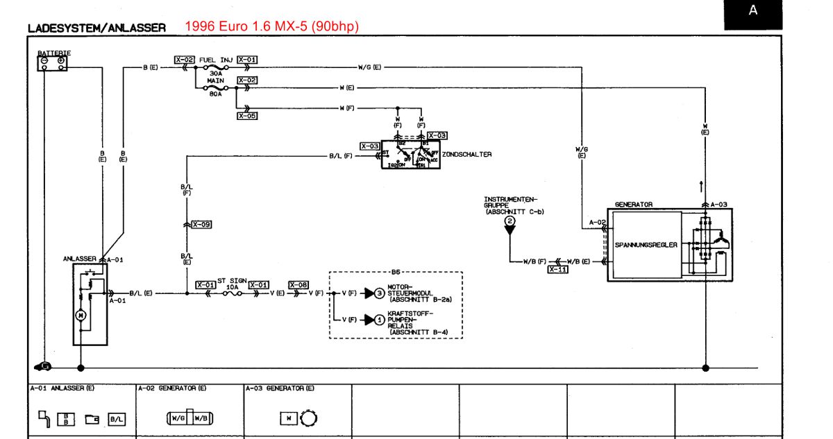
Here is the alternator wiring on the 1996 car:
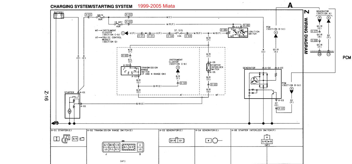
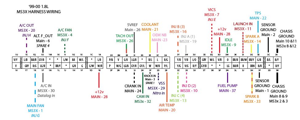
Here is the wiring on the 1999+ cars:
I have the field wire on the "spare" 16pin connector on my MS3 - now I need to pull a wire and wire it to? (My guess would be the W/G - wire on the 96 car? - Is this correct?)
P.S.: I have no problem if you tell me that I am stupid an should do things how they are always done - aka swap in the old internally regulated alt...
Thanks
I have a thread going on with my 1996 (90bhp) Euro 1.6 to VVT swap attempt.
Here: https://www.miataturbo.net/engine-pe...uro-car-72134/
Now I re-wired my MS3 + MS3x (DIY Frank's PNP style) from my 99-00 car for the 1996 wiring (which is nearly identical to the 1990-93 wiring, apart from already being sequential injection) according to this schematic:
Now I need some help about the alternator wiring.
I do have in fact an spare 1.8 94-97 alternator here - just in case.
But as I do already have a working alternator circuit inside my MS3, I would like to check the possibilities to use it, but as I am no electronic expert I need some help.
Here is the alternator wiring on the 1996 car:
Here is the wiring on the 1999+ cars:
I have the field wire on the "spare" 16pin connector on my MS3 - now I need to pull a wire and wire it to? (My guess would be the W/G - wire on the 96 car? - Is this correct?)
P.S.: I have no problem if you tell me that I am stupid an should do things how they are always done - aka swap in the old internally regulated alt...
Thanks

Reply
 0
0

0
06-19-2013, 04:28 AM
#2

Have you checked the connector on the alternator?
The connector for an alt with internal control is different (go figure).
Your harness have simply the connection to the charging light in that connector, not something to the ECU which will enable connection to field control.
A 94-97 alt must be the easiest choice (connector might even be the same).
Sell the NB alt.
Reply
0
0
06-19-2013, 07:17 AM
#3
Boost Czar


iTrader: (62)
Join Date: May 2005
Location: Chantilly, VA
Posts: 79,501
Total Cats: 4,080
I think he can do what he's talking about, But I think it would require fussing around with the wiring at the connector.
Right now Here's what you have:
What you'll need to do:
Right now Here's what you have:
Code:
L	R
W/G	W/B
12v	Bat. Lgt.
Code:
L	R
W/G	W/B
F_Out	12v
Reply
0
0
01-13-2016, 06:42 AM
#4
Junior Member

Join Date: Jan 2016
Location: Munich
Posts: 362
Total Cats: 93
resurrecting an old thread, I wanted to clarify/ask a few things.
I'm in the middle of a VVT into 91 NA swap myself. My ECU is a MS3-Pro using Westfieldmx5's custom board. It's made for a 90-93 MX-5 and unses the original ECU connector.
I want to use the internal alternator control circuit that I still have to solder to the board. Once I'm done building the circuit, how do I connect it to my ECU? If I understand Braineack correctly, I have to
- run the White/Green wire (99-00 wiring harness color) from the 99 alternator to the F_Out pin at the ECU, and
- run the White/Blue wire (99-00 wiring harness color) from the 99 alternator to the 12V pin at the ECU
But since my 90-93 pinout doesn't have a F_Out pin, i can randomly pick on. In my case, I could pick connector pin 1D of the 90-93 ECU connector, run a wire jumper over to the 99-00 side of the board and connect it to the hole 1O of the not-installed 99-00 ECU connector.
1O should be connected to the internal alternator circuit of the board, right? I guess so, because in the 99-00 pinout the pin 1O (GY/R color wire) is labelled as "Alt. F_Out"
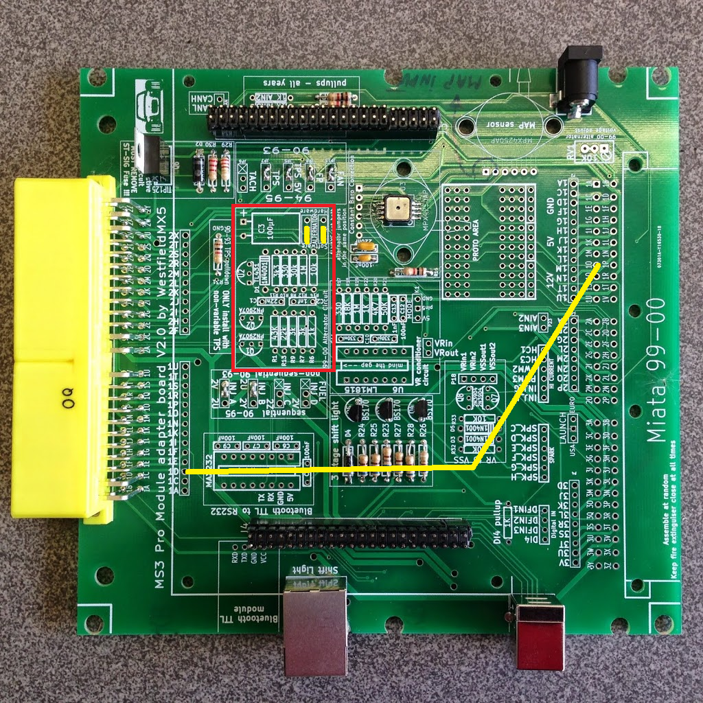
yellow jumper wire to get alternator F_Out from 1O (99-00 connector) to unused pin 1D at 90-93 connector
1D (W/G) seems to be free, ready to be the future Alt. F_Out pin
Please be kind to me. You're talking to a mechanically skilled guy who still has to get comfortable with electric circuits
I'm in the middle of a VVT into 91 NA swap myself. My ECU is a MS3-Pro using Westfieldmx5's custom board. It's made for a 90-93 MX-5 and unses the original ECU connector.
I want to use the internal alternator control circuit that I still have to solder to the board. Once I'm done building the circuit, how do I connect it to my ECU? If I understand Braineack correctly, I have to
- run the White/Green wire (99-00 wiring harness color) from the 99 alternator to the F_Out pin at the ECU, and
- run the White/Blue wire (99-00 wiring harness color) from the 99 alternator to the 12V pin at the ECU
But since my 90-93 pinout doesn't have a F_Out pin, i can randomly pick on. In my case, I could pick connector pin 1D of the 90-93 ECU connector, run a wire jumper over to the 99-00 side of the board and connect it to the hole 1O of the not-installed 99-00 ECU connector.
1O should be connected to the internal alternator circuit of the board, right? I guess so, because in the 99-00 pinout the pin 1O (GY/R color wire) is labelled as "Alt. F_Out"
yellow jumper wire to get alternator F_Out from 1O (99-00 connector) to unused pin 1D at 90-93 connector
1D (W/G) seems to be free, ready to be the future Alt. F_Out pin
Please be kind to me. You're talking to a mechanically skilled guy who still has to get comfortable with electric circuits
Reply
0
0
01-13-2016, 08:14 AM
#5
Boost Czar
iTrader: (62)
Join Date: May 2005
Location: Chantilly, VA
Posts: 79,501
Total Cats: 4,080
tap any white/red wire in the engine bay for 12v.
I'd send F_OUT to 2X to the purge valve solenoid wire.
1D goes to the diagnositcs connectors. although you could tap B+ right there as well for your 12v.
I'd send F_OUT to 2X to the purge valve solenoid wire.
1D goes to the diagnositcs connectors. although you could tap B+ right there as well for your 12v.
Reply
0
0
01-13-2016, 09:09 AM
#6
Junior Member
Join Date: Jan 2016
Location: Munich
Posts: 362
Total Cats: 93
Thanks a lot!
Why not hook up the 12v wire from the 90-93 alternator connector (on the harness side) to the corresponding pin of the 01-05 alternator?
... hm I originally wanted to use that wire for the VVT signal. So I'd have to run an extra wire from the ECU, either for VVT function or alternator function.
Would that leave me with a non-functional battery warning light?
Reply
0
0
01-13-2016, 09:26 AM
#7
Boost Czar
iTrader: (62)
Join Date: May 2005
Location: Chantilly, VA
Posts: 79,501
Total Cats: 4,080
whoops i was combining the concept of adding VVT and alternator.
ignore me. too early. ill review again in a bit.
if you dont have the alternator yet, I'd go for an internally regulated 94-97 one over the NB alternator.
EDIT: reread, what youre doing looks good. Id' still just recomend using a 94-97 alt over an 99+
ignore me. too early. ill review again in a bit.
if you dont have the alternator yet, I'd go for an internally regulated 94-97 one over the NB alternator.
EDIT: reread, what youre doing looks good. Id' still just recomend using a 94-97 alt over an 99+
Last edited by Braineack; 01-13-2016 at 11:18 AM.
Reply
1
1
01-13-2016, 05:01 PM
#8
Senior Member

Join Date: Nov 2007
Location: Belgium
Posts: 999
Total Cats: 73
If you're going to install a VVT engine, don't forget to remove the tps resistor you have on the board!
The yellow wire to the 99 side is correct. The 2 yellow jumpers in the alternator area are correct as well. Choose software when you want hardware
The yellow wire to the 99 side is correct. The 2 yellow jumpers in the alternator area are correct as well. Choose software when you want hardware
Last edited by WestfieldMX5; 01-13-2016 at 05:21 PM.
Reply
1
1
01-13-2016, 06:13 PM
#9
Junior Member
Join Date: Jan 2016
Location: Munich
Posts: 362
Total Cats: 93
While you're here, could you quickly answer two questions please:
- for sequential injection i desolder the two jumper wires and connect "Inj A middle hole" + 2U hole // "Inj B middle hole" + "Y // Inj C m.h." + 2Z // "Inj D" + 2V, right? (plus using the correct pins at the ECU connector of course)
- do i still have to install a jumper wire at the AFM connector to make the fuel pump work? Or is it already taken care of by having the jumper wire installed on the board at JB8?
- how do I get the internal BT module connected to my laptop for the first time? I suppose it won't simply be available when I power up the ECU?
Reply
0
0
01-14-2016, 02:35 PM
#10
Senior Member
Join Date: Nov 2007
Location: Belgium
Posts: 999
Total Cats: 73
Correct about the injector jumpers. And indeed, you'll have to rewire the 4 injectors for the correct pins on the connector)
There's 2 ways to make the fuel pump work:
1. use the jumper
OR
2. remove st-sig fuse and build the active fuel pump circuit what you appear to have done
Is this a BT that I supplied? If so, it is already programmed. If not, you'll have to program it according to the manufacturers manual.
Send me a PM with your email address and I'll send you some setup info about my board.
Reply
0
0

Thread
Thread Starter
Forum
Replies
Last Post
Zaphod
MEGAsquirt
47
10-26-2018 11:00 PM


