
MSPNP v3.57 Upgrade Help to MS2


Reply
 0
0

0
Reply
0
0
Reply
0
0
it must have been your adjustment of the pots.
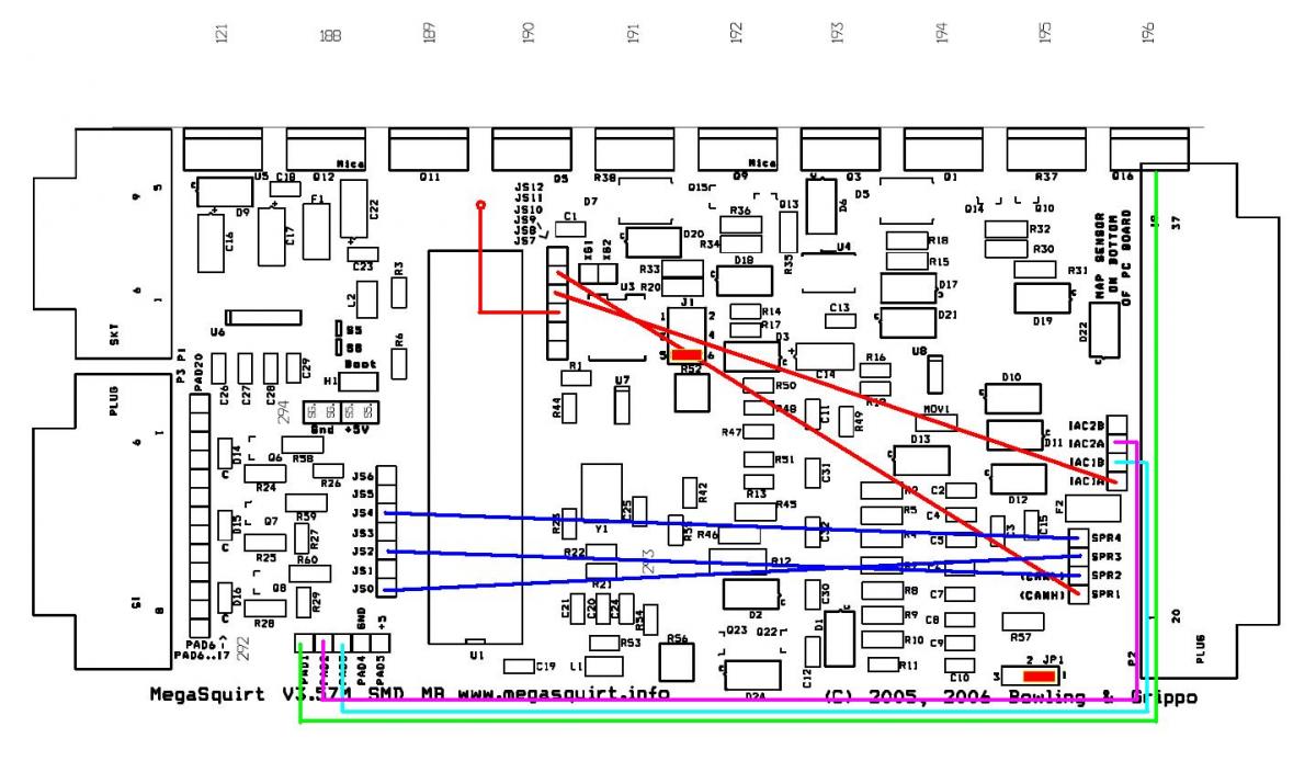
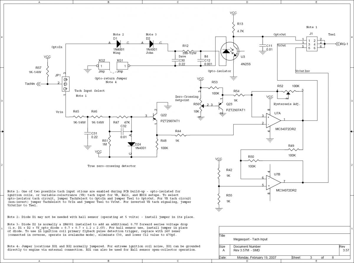
the crank signal comes in pin24, which is tachin. This goes to the JP1 jumper and that should be on 1-2, that should have been changed from 2-3. Then the signal goes through the VR conditioner circuit and those adjustment pots, and then out to J1 through 5-6 which sends the signal to the CPU. This should have been moved from 1-2. Right?
you need to spin both 6 turns CCW, then turn the bottom one, r56, back two or 3 turns clockwise.
Reply
0
0
it must have been your adjustment of the pots.
the crank signal comes in pin24, which is tachin. This goes to the JP1 jumper and that should be on 1-2, that should have been changed from 2-3. Then the signal goes through the VR conditioner circuit and those adjustment pots, and then out to J1 through 5-6 which sends the signal to the CPU. This should have been moved from 1-2. Right?
you need to spin both 6 turns CCW, then turn the bottom one, r56, back two or 3 turns clockwise.

I think I may try and see if I can try and measure with a multimeter any signal on 5-6 so ideally I can see if the pots are allowing signal through. Ill be back with results.
Reply
0
0
Sweet so I was able to dial in the pots with the multimeter(so I think). Actually if anyone knew the exact v's on both that would be sweet but nonetheless the pots are working. I still have no crank signal and 5-6 shows nothing as far as v's or analog resistance.
Reply
0
0
Reply
0
0
get it closer to 3v, then see if you get the crank signal on the composite log. Cause that's the only thing holding you up, the rest of the jumpers are unrelated and youre getting the cam signal.
Reply
0
0

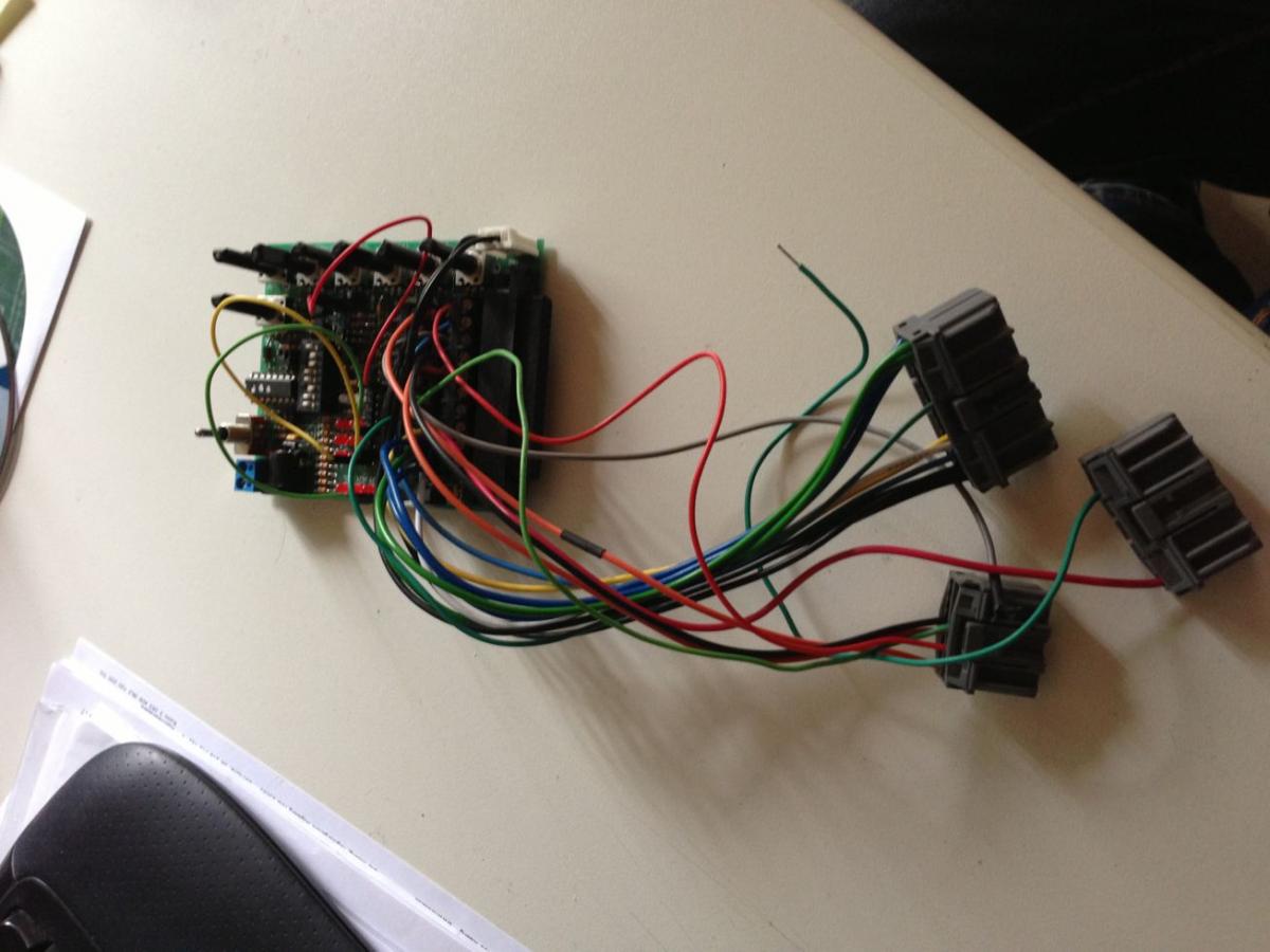
you can do that, I typically will just use wire with the correct female contacts to bring in power, ground, crank trigger and the second trigger to sync on a DIYPNP or MSPNP.
Reply
0
0
Still no crank signal. I tried it at 3v, 3.5v, 4v, 4.5v, and 5v. Still nothing. Something else in the circuit has to be wrong. luckily I have been using a gel cell optima battery out of my truck or the battery would be dead by now.
Reply
0
0
There's not much to it:
Pin 24 (the crank input) is Tachin.
that goes through the VR circuit and out to IRQ-1 (cpu), so the only thing to it is the two jumpers and the adjustment of the pots.
The JP1 2-3 jumper and J1 1-2 jumper should have been severed, else that would cause issue.
Pin 24 (the crank input) is Tachin.
that goes through the VR circuit and out to IRQ-1 (cpu), so the only thing to it is the two jumpers and the adjustment of the pots.
The JP1 2-3 jumper and J1 1-2 jumper should have been severed, else that would cause issue.
Reply
0
0


