
Need help with alternator circuit Franks MS3pro adapter


Thread Starter
Elite Member
Joined: Mar 2006
Posts: 1,574
Total Cats: 106
From: Schwarzenberg, Germany
Hi guys,
I need some help with the 99-00 Alternator circuit.
I got one of Franks ingenious adapter boards for the MS3 pro and everything is working fine - apart from the Alternator circuit not working.
I emailed Frank a couple of times and send him a PM on here, but he did not respond (I hope he is well and I didn't do anything wrong... )
)
Could one of the electronics experts please help me out on where I would have to check voltages/resistances on the circuit.
Here is the alternator PCB from Frank:

And here is a picture of the MS3pro board:
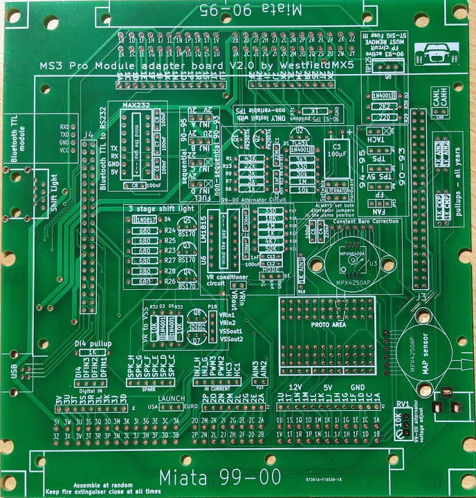
The naming of the parts is a little different on the MS3pro board, but the circuit should be the same...
Here you can see my unit working and talking to TS via the onboard Bluetooth.

As I am no electronics expert it would be nice if you could tell me - with a +12V source attached - which voltages should I be reading on which part/leg!
Edit: I know that there is a silkscreen error on the board and the jumpers are set correctly...
Any help is appreciated!
I need some help with the 99-00 Alternator circuit.
I got one of Franks ingenious adapter boards for the MS3 pro and everything is working fine - apart from the Alternator circuit not working.
I emailed Frank a couple of times and send him a PM on here, but he did not respond (I hope he is well and I didn't do anything wrong...
) Could one of the electronics experts please help me out on where I would have to check voltages/resistances on the circuit.
Here is the alternator PCB from Frank:
And here is a picture of the MS3pro board:
The naming of the parts is a little different on the MS3pro board, but the circuit should be the same...
Here you can see my unit working and talking to TS via the onboard Bluetooth.
As I am no electronics expert it would be nice if you could tell me - with a +12V source attached - which voltages should I be reading on which part/leg!
Edit: I know that there is a silkscreen error on the board and the jumpers are set correctly...
Any help is appreciated!
Reply
 0
0

0


do you have a power supply?
with more than 15v in to the unit, the field output should drop below 3v.
with less than ~14.2v in to the unit, the field output should rise to over 9v.
with more than 15v in to the unit, the field output should drop below 3v.
with less than ~14.2v in to the unit, the field output should rise to over 9v.
Reply
0
0
Thread Starter
Elite Member
Joined: Mar 2006
Posts: 1,574
Total Cats: 106
From: Schwarzenberg, Germany
Unfortunately I don't have a variable power supply, only the Jimstim with a 12V supply.
But the field output only gives a reading of 0.08V.... So I need to check which of the parts of the circuit might be broken...
Greets
But the field output only gives a reading of 0.08V.... So I need to check which of the parts of the circuit might be broken...
Greets
Reply
0
0

Why not use MS3-Pro's built in alternator control function? It's very configurable and works awesome.

Reply
0
0
Thread Starter
Elite Member
Joined: Mar 2006
Posts: 1,574
Total Cats: 106
From: Schwarzenberg, Germany
I checked the thread about it... but didn't know if that was working correctly, the thread was a little bi-polar about that....
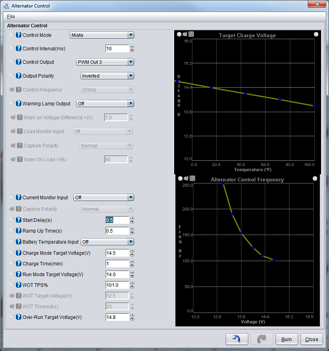
What would the correct settings for the Miata do look like?
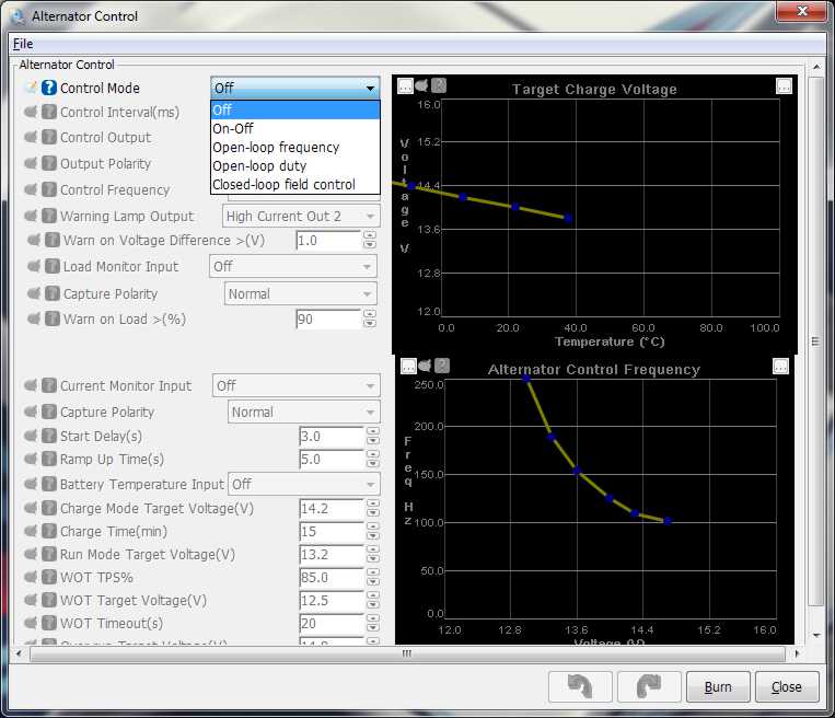
Because my MS3pro Alternator control setting looks different and has no "Miata" mode...
From the thread:
Mine:
What would the correct settings for the Miata do look like?
Because my MS3pro Alternator control setting looks different and has no "Miata" mode...
From the thread:
Mine:
Reply
0
0
it works great actually.
haven't checked the MS3PRO firmware, but in regular MS3 it's labeled "high speed field control". Maybe you need the latest ms3pro firmware? or use that closed-loop field control one; that's probably it.
All you need to have is a 5v pull-up on the output that you use. IIRC I used a 100ohm or 270ohm resistor.
Looks like it would incredibly easy to get working on that adapter board.
Reply
0
0
Thread Starter
Elite Member
Joined: Mar 2006
Posts: 1,574
Total Cats: 106
From: Schwarzenberg, Germany
I don't know if Frank already has that 5V pullup on the adapter-board (but it doesn't look like).
So I would just need to wire said resistor between 5V and pin 1O - which is the alternator field output on the 99-00?
(100 ohm or 270 ohm - I got both)
Edit: BTW. I am on the latest Firmware...
So I would just need to wire said resistor between 5V and pin 1O - which is the alternator field output on the 99-00?
(100 ohm or 270 ohm - I got both)
Edit: BTW. I am on the latest Firmware...
Last edited by Zaphod; Oct 7, 2014 at 09:43 AM.
Reply
0
0

Newb
Joined: May 2013
Posts: 32
Total Cats: 3
From: Yes. There really is a Kalamazoo!
Check that all of the resistors are of the specified value. I got one of Franks kits this spring and found that R7 (supposedly 1m) actually measured 10k, even though it was banded as a 1m.
Reply
0
0
Thread Starter
Elite Member
Joined: Mar 2006
Posts: 1,574
Total Cats: 106
From: Schwarzenberg, Germany
Franks board utilizes the Stepper out 1 for the software alternator control - if I read this correctly on the alternator control thread - this is wrong as you need an PWM output - correct?
Reply
0
0
Use any spare PWM output and High Speed Field Control mode. It was only called Miata mode while we were developing it. A 5V pullup is needed. That's it.
Reply
0
0
Thread Starter
Elite Member
Joined: Mar 2006
Posts: 1,574
Total Cats: 106
From: Schwarzenberg, Germany
So I will do as you suggested.
Do I use the standard settings for the High speed field mode? Or do I have to set something Miata specific?
Reply
0
0
Thread Starter
Elite Member
Joined: Mar 2006
Posts: 1,574
Total Cats: 106
From: Schwarzenberg, Germany
O.K. I just soldered the new software alternator control and will report...
At the stim with an INput voltag of ~12V the field output reads ~4,85V.
O.K. Just tested it out. It charges a tad on the high side.
With the above voltage settings in run mode it charges at 14.9 V (Tuner Studio reading) - 15.3V on my Maxigauge. (But its very stable there!)
Could this be related with the battery voltage calibration? I never could wrap my head around how I would set this up with
a standard multimeter and no other equipment - because I never know what the Supply voltage at Zero ADC Count or at Max ADC count is...
Any other suggestions on how the get this to charge at the correct target voltage?
Edit:
I found this advice from Matt at msextra.com about the voltage calibration
and tried to do this on my car. Now my Maxigauge, Tuner Studio and Multimeter read the same voltage.
The alternator charges at 13.6-13.7V now, which is fine by me, but should the Alternator control not try to get to the Target of 14.0V?
Just a thought - is the TS reading and the voltage that MS measures the same, or could that be the difference between reading and target.
Thanks
At the stim with an INput voltag of ~12V the field output reads ~4,85V.
O.K. Just tested it out. It charges a tad on the high side.
With the above voltage settings in run mode it charges at 14.9 V (Tuner Studio reading) - 15.3V on my Maxigauge. (But its very stable there!)
Could this be related with the battery voltage calibration? I never could wrap my head around how I would set this up with
a standard multimeter and no other equipment - because I never know what the Supply voltage at Zero ADC Count or at Max ADC count is...
Any other suggestions on how the get this to charge at the correct target voltage?
Edit:
I found this advice from Matt at msextra.com about the voltage calibration
Usually you should set the zero ADC reading to the difference between the ECU ground voltage and battery ground voltage, and adjust the top number to get the readings to match.
The alternator charges at 13.6-13.7V now, which is fine by me, but should the Alternator control not try to get to the Target of 14.0V?
Just a thought - is the TS reading and the voltage that MS measures the same, or could that be the difference between reading and target.
Thanks
Last edited by Zaphod; Oct 8, 2014 at 06:39 AM.
Reply
0
0
Thread Starter
Elite Member
Joined: Mar 2006
Posts: 1,574
Total Cats: 106
From: Schwarzenberg, Germany
The alternator charges at 13.6-13.7V now, which is fine by me, but should the Alternator control not try to get to the Target of 14.0V?
Just a thought - is the TS reading and the voltage that MS measures the same, or could that be the difference between reading and target.
Thanks
Just a thought - is the TS reading and the voltage that MS measures the same, or could that be the difference between reading and target.
Thanks
Reply
0
0
Thread Starter
Elite Member
Joined: Mar 2006
Posts: 1,574
Total Cats: 106
From: Schwarzenberg, Germany
 I want things to work the way I want. If I command the MS a target of 14.0V I want a result of 14.0V.... Not some itsy - I give it a target of 14.4V and it gives me my desired 14.0V....
Reply
0
0

Senior Member
Joined: Nov 2007
Posts: 999
Total Cats: 73
From: Belgium
Have had some personal issues. Am back.
Sven, I'm using hardware control. I got software working by using a different output, but like you, voltage does not correspond with the settings. I don't like to use a fudge factor to get it right so I reverted back to hardware. Tunerstudio was set at 14.3V, but logs showed voltage fluctuationg between 14.7 and 15.1V, too high and too much fluctuation for my ease of mind.
Hardware is rock solid within .2V
It works on my car without issues. I'll look up the schematics and send you a copy so you can trace the circuit.
Last edited by WestfieldMX5; Oct 9, 2014 at 08:26 AM.
Reply
0
0
Senior Member
Joined: Nov 2007
Posts: 999
Total Cats: 73
From: Belgium
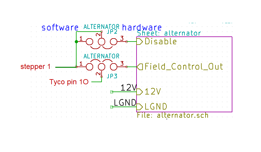
Here's the schematic of the MS3 Pro board.
With both jumpers set in 1&2 position, you're using software control.
Stepper 1 of the Pro module is now directly connected to pin 1O.
Of course, this board was designed before I knew that we had to use a PWM output. So cut the trace from Stepper 1 of the Pro module to pin 1 of JP3 and bring a PWM output to pin 1 of JP3 instead. Also add a 5V pullup to that wire because I didn't add one in my design (again, I didn't know yet that this was necessary).
Or, do as Scott said, remove both jumpers and just run a wire from PWM2 on the board to 1O, add the pullup and be done.
With both jumpers set in 2&3 position, you're using hardware control.
Stepper 1 is now connected to the disable pin of my circuit. This means that when you activate stepper 1, the alternator will not charge (100%tps, rpm < 500 rpm etc etc). In this situation, there's no need to use a PWM output, Stepper 1 is fine.
The field control output of the hardware circuit is now connected to Tyco 1O and regulates the voltage.
Last edited by WestfieldMX5; Oct 9, 2014 at 08:46 AM.
Reply
0
0

Thread
Thread Starter
Forum
Replies
Last Post
Zaphod
MEGAsquirt
47
Oct 26, 2018 11:00 PM
StratoBlue1109
Miata parts for sale/trade
21
Sep 30, 2018 01:09 PM
hi_im_sean
Miata parts for sale/trade
1
Sep 16, 2015 12:45 PM


