
Need help finalizing my MS2 jumper harness.


Thread Starter
Junior Member
Joined: Aug 2011
Posts: 45
Total Cats: 0
From: Ottawa,Ontario
I have a few questions regarding some final connections required to complete my MS jumper harness.Its my first time working with MS and working on electrical is not my my strong my point ,so please bear with me.
This is what i'm dealing with :
harness being built for a 1990 miata
MS2 ecu
Pre-built pigtail harness from DiyAutotune
To build my harness i've followed the 90-93 wiring diagram found on the MS wiki. Link here http://www.boostedmiata.com/gallery2...ne_harness.jpg
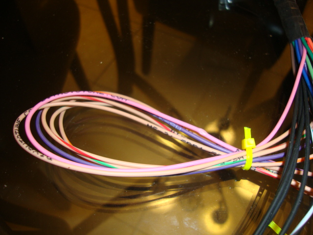
Here is what I have up to now.(don't mind all the zip ties)
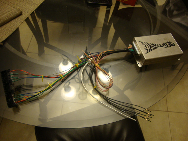
These are the current slots that are not soldered up yet:
-2C sensor ground
-2A chassis gorund
-2D sensor ground
-2B Chassis ground
-2E "thick gray CAS"
-1C 12+v output for fuel pump.
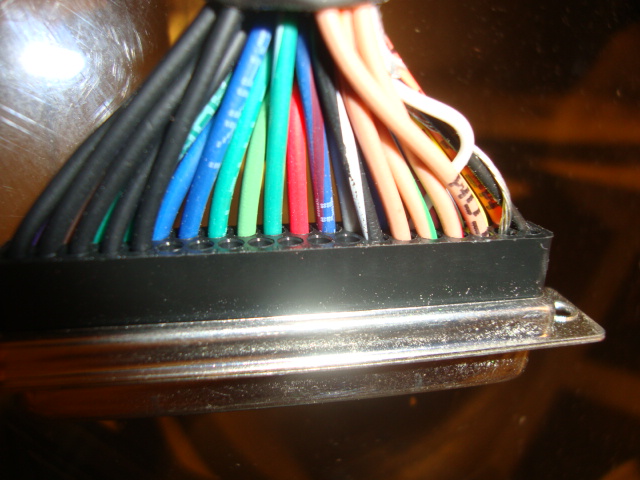
Q#1. First of all , the diyautotune harness has 6 ground wires and I'm not sure which of them should join into (2c,2a,2d,2b).

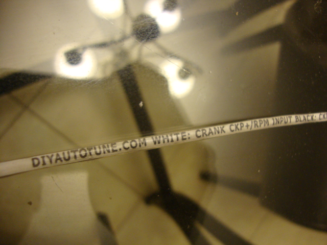
Q#2. Is the 2E input on the ecu plug which is marked "Thick gray CAS" supposed to be joined in by the 3 wire bundle from the Diyautotune harness(white wire,black wire and unshielded wire)?
Q#3.For the 12v+ fuel pump output in 1C, can I run the the "beige/pink" wire that's already in pin 6 on the db37 to 1c?
Thank you.
This is what i'm dealing with :
harness being built for a 1990 miata
MS2 ecu
Pre-built pigtail harness from DiyAutotune
To build my harness i've followed the 90-93 wiring diagram found on the MS wiki. Link here http://www.boostedmiata.com/gallery2...ne_harness.jpg
Here is what I have up to now.(don't mind all the zip ties)
These are the current slots that are not soldered up yet:
-2C sensor ground
-2A chassis gorund
-2D sensor ground
-2B Chassis ground
-2E "thick gray CAS"
-1C 12+v output for fuel pump.
Q#1. First of all , the diyautotune harness has 6 ground wires and I'm not sure which of them should join into (2c,2a,2d,2b).
Q#2. Is the 2E input on the ecu plug which is marked "Thick gray CAS" supposed to be joined in by the 3 wire bundle from the Diyautotune harness(white wire,black wire and unshielded wire)?
Q#3.For the 12v+ fuel pump output in 1C, can I run the the "beige/pink" wire that's already in pin 6 on the db37 to 1c?
Thank you.
Reply
 0
0

0


Thread Starter
Junior Member
Joined: Aug 2011
Posts: 45
Total Cats: 0
From: Ottawa,Ontario
Thank you for your reply Scott.
Any tips on what to do with the other 2 wires (question 2,3 of my initial post)?
I've noticed quite a few of the wires on the DiyAutotune pigtail do not mach with the colors on the db37 build write up.
Any tips on what to do with the other 2 wires (question 2,3 of my initial post)?
I've noticed quite a few of the wires on the DiyAutotune pigtail do not mach with the colors on the db37 build write up.
Reply
0
0
q2, match the pins. 2E goes to pin 24. 2G goes to pin 25.
q3, did you build the high side driver circuit? it's easier to run the purple fuel pump wire to 2O and then jump it at the AFM connector like so:

q3, did you build the high side driver circuit? it's easier to run the purple fuel pump wire to 2O and then jump it at the AFM connector like so:
Reply
0
0
Thread Starter
Junior Member
Joined: Aug 2011
Posts: 45
Total Cats: 0
From: Ottawa,Ontario
I've already connected 2E to pin 25.
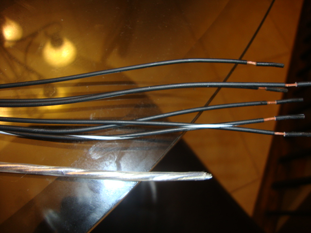
My concern with the wire in pin 24 is that it contains a bundle of 3 wires in total.1 white,1 black and one exposed wire.Am I supposed to solder all three wires to 2E?
For Q3 ,the purple wire is definately an easy solution.But if the board has already been modified , can I use the wire thats in pin 6 on the piftail to 1c?The Ms was built by member wayne_curr for his 1.6,I'm pretty sure he has already done the tip125 mod.I'll have to open it up and see.
Reply
0
0
no, just use one dude.
it'll go out one of the spare ports, so you gotta match it. I cant hand hold that part. figure out where the output of the tip125 goes, match that wire for your harness.
it'll go out one of the spare ports, so you gotta match it. I cant hand hold that part. figure out where the output of the tip125 goes, match that wire for your harness.
Reply
0
0
Thread Starter
Junior Member
Joined: Aug 2011
Posts: 45
Total Cats: 0
From: Ottawa,Ontario
Thank you for your patience Scott,
This is the bundled wire I was talking about. So only the white goes in 2E , the black and un-covered wire remain free?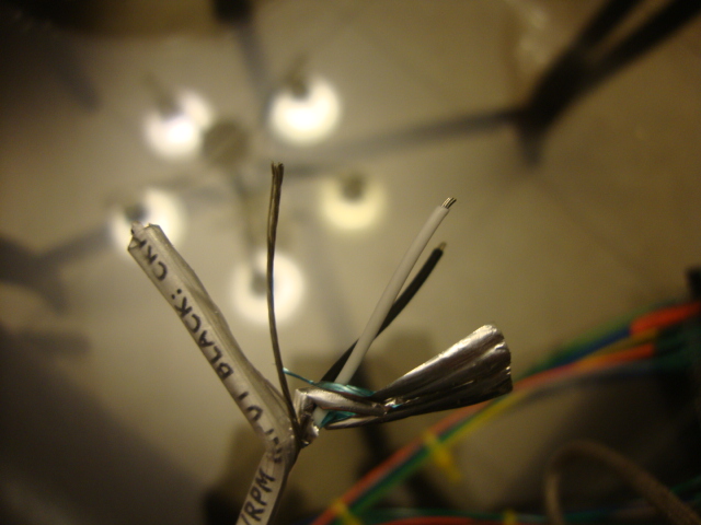
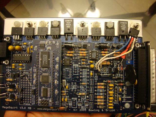
I checked out the board and tip125 has not been modified.Does this mean I can use the purple wire/afm crossover method instead?
This is the bundled wire I was talking about. So only the white goes in 2E , the black and un-covered wire remain free?
I checked out the board and tip125 has not been modified.Does this mean I can use the purple wire/afm crossover method instead?
Reply
0
0
yeah, so it's the standard fuel pump output...so a ground.
and you run it to 2O.
2O goes back to the AFM connector. Since the AFM is what grounds the fuel pump relay, you take the singal from 2O and jump it to the pin that normally grounds the relay.
otherwise, you build that driver cricuit and send 12v out a tip125 to 1C and remove the ST-SIGN fuse.
or you just run the purple fuel pump wire directly to the fuel pump relay under the steering column in the dash to the lt. green wire.
but do you understand what I'm saying about the 12v output for the 1C spot? you have to build a custom circuit and send the output somwhere, usually on one of the spare 1-4 spots. So you have to pick which wire in your db37 connector that matches where you stuck the output in the MS. then you can run that wire to 1C. Without know where the circuit goes right now, I cant tell you which wire to use.
I don't see that mod built in your MS anyways.
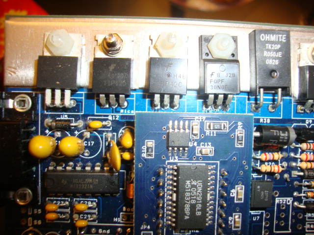
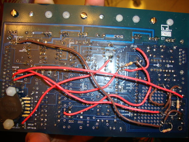
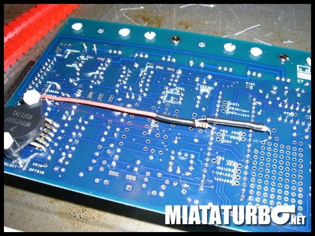
your mods on the baord look good, I just dont like how exposed the wire going from IAC to js10 is, just make sure it doesn't touch anything else. If it touches the js9 in which it's going directly over, you will probably fry the MS2 CPU.
I aim to keep my mods very clean:

and you run it to 2O.
2O goes back to the AFM connector. Since the AFM is what grounds the fuel pump relay, you take the singal from 2O and jump it to the pin that normally grounds the relay.
otherwise, you build that driver cricuit and send 12v out a tip125 to 1C and remove the ST-SIGN fuse.
or you just run the purple fuel pump wire directly to the fuel pump relay under the steering column in the dash to the lt. green wire.
but do you understand what I'm saying about the 12v output for the 1C spot? you have to build a custom circuit and send the output somwhere, usually on one of the spare 1-4 spots. So you have to pick which wire in your db37 connector that matches where you stuck the output in the MS. then you can run that wire to 1C. Without know where the circuit goes right now, I cant tell you which wire to use.
I don't see that mod built in your MS anyways.
your mods on the baord look good, I just dont like how exposed the wire going from IAC to js10 is, just make sure it doesn't touch anything else. If it touches the js9 in which it's going directly over, you will probably fry the MS2 CPU.
I aim to keep my mods very clean:
Reply
0
0

Thread
Thread Starter
Forum
Replies
Last Post
StratoBlue1109
Miata parts for sale/trade
21
Sep 30, 2018 01:09 PM


