When you click on links to various merchants on this site and make a purchase, this can result in this site earning a commission. Affiliate programs and affiliations include, but are not limited to, the eBay Partner Network.
1990 Mazda Miata
No AC, has stock TPS, will have GM IAT
Hey everybody,
So I ended up purchasing a parts car that had a bunch of turbo bits, and some goodies that made it worth it to buy it and part it out.
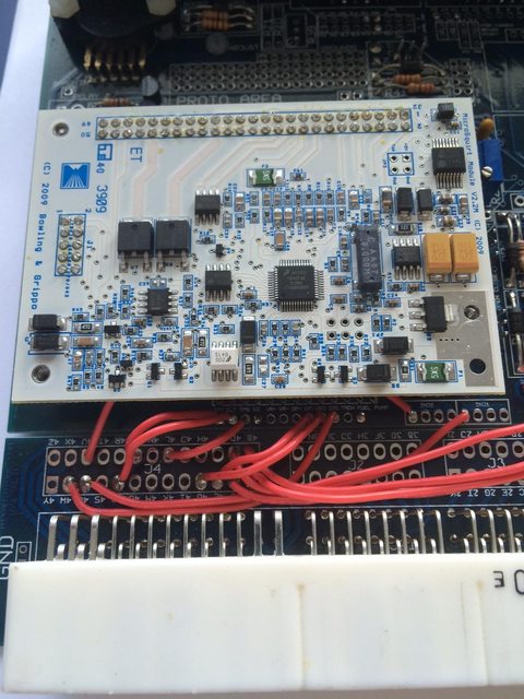
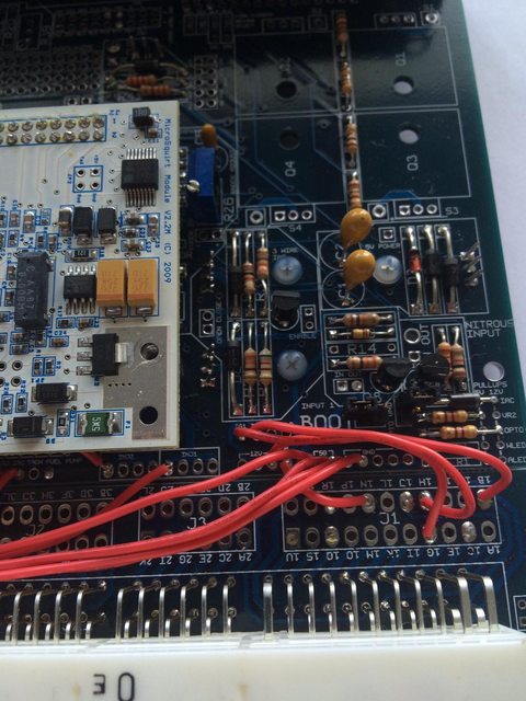
Surprisingly enough, the car had a Megasquirt DIYPNP sitting in the trunk when i picked it up, but was still running on stock ecu.. I later found out the previous owner to who I purchased it from had bought it, and the owner after had never bothered to install it..
So I pulled the ecu apart and started checking wiring, and it seemed to match up to a 90-93 Miata, but with some variation.
I was wondering if somebody could give me some insight on what these differences in wiring may mean. I have done my research and sorted out a few, would just like to get a second opinion.
I've modified the table to show what connections my car has.
Just wondering if anybody can help me out with this!
Really excited to get my car running on this, but want to verify everything before I install it and turn the key.
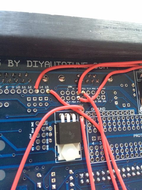
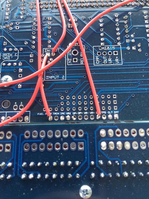
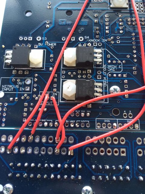
Picture of my chicken scratch
*** ANYTHING HIGHLIGHTED MEANS THE CONNECTION MATCHES ***
**** STRIKE OUT INDICATES SOMETHING THAT IS DIFFERENT FROM GUIDE ****
So, as far as I know..
ECU Is set up for a
Variable TPS
Wideband O2 Sensor Wired to DB15 pin 15
Boost Control Solenoid
Possibly Launch Control?
upload some pics of it also. picture can be worth a 1000 words.
Hey thanks for replying so quickly to this.
I will upload the pictures I have so far, but I will get some more detailed images tonight.
I know these are terrible but they will have to do for now!
What happens if I do nothing about the A/C Circuit and leave it wired as it?
The A/c will work as wired, but the MS is not in the loop. They've added a/c controls to the firmware since that unit was built, so you can input the a/c switch into the MS and then the MS can turn on the a/c compressor. Then there's idle up code that you can tune that opens the idle valve and target rpm speed so it's a seamless activation. Otherwise CL idle is reactive and the sudden increase in load and drop in voltage can cause the idle code to dip and become unstable momentarily -- however the improved idle code like the adaptive timing and and voltage pwm% compensation might actually be perfectly sufficient without a/c idle up.
The A/c will work as wired, but the MS is not in the loop. They've added a/c controls to the firmware since that unit was built, so you can input the a/c switch into the MS and then the MS can turn on the a/c compressor. Then there's idle up code that you can tune that opens the idle valve and target rpm speed so it's a seamless activation. Otherwise CL idle is reactive and the sudden increase in load and drop in voltage can cause the idle code to dip and become unstable momentarily -- however the improved idle code like the adaptive timing and and voltage pwm% compensation might actually be perfectly sufficient without a/c idle up.
In my cars situation, it does not have AC, does this still need to be done?
Also for updating firmware, is it as easy as updating it through tunerstudio, or do I have to add in the boot jumper, use megasquirt software to update the firmware etc.
I tried following some tutorials, but I didn't have enough time to figure everything out. Seemed like I needed a megasquirt based software to do so, not tuner studio.


 0
0