
Resurrecting a "dead" MS3 - Questions


just take it one step at a time.
you have it built, firmware loaded, you're just not syncing becuase you're only inputting the crank trigger and it's not seeing a cam trigger.
you have it built, firmware loaded, you're just not syncing becuase you're only inputting the crank trigger and it's not seeing a cam trigger.
Reply
 0
0

0

Thread Starter
Senior Member
Joined: Dec 2007
Posts: 1,467
Total Cats: 132
From: ATL
I "caved" - MS3X card ordered...it'll come just in time for me to go out of town so I'm dead in the water until next week. That will give me enough time to figure out building the alternator control circuit (eek!!).
Reply
0
0
Thread Starter
Senior Member
Joined: Dec 2007
Posts: 1,467
Total Cats: 132
From: ATL
'99
Weighing the complexity of building the alternator regulation circuit (electronics..eek, soldering...eek) versus putting in a NA alternator with some (seemingly minimal) wiring changes (safe mechanical stuff, electrical noob-level wire splicing).
Right now, I'm leaning towards the latter.
Weighing the complexity of building the alternator regulation circuit (electronics..eek, soldering...eek) versus putting in a NA alternator with some (seemingly minimal) wiring changes (safe mechanical stuff, electrical noob-level wire splicing).
Right now, I'm leaning towards the latter.
Reply
0
0
Thread Starter
Senior Member
Joined: Dec 2007
Posts: 1,467
Total Cats: 132
From: ATL
I am "back in the saddle again" (sort of).
I got the expander board and plugged it in and...nothing - no RPM signal. No matter how I tweaked R52 and R56 I got nothin'.
So, I plugged in my (brand new, el cheapo DSO201 scope (don't laugh) to try to trace down the RPM signal coming from the jimstim. I could see a nice, strong RPM signal on the jimstim board that varied with turning the coarse and fine RPM pots. But when I started at the Tsel jumper on the MS mainboard I got a weird, almost non-existent signal at that jumper (it was down in the weeds and didn't change with changes in the RPM signal).
Digging into the MS schematics, I could see that the signal to Tsel comes from IRQ-1, and pouring through the schematics shows that IRQ-1 comes from U1, the big IC on the daughterboard. That's where I stopped, because that would lead me to believe that the IC (or something) on the daughterboard is fried. As a double-check, I put the scope probe onto pin 17 of JP2 on the daughterboard and got the same signal that I saw on Tsel (naturally, I think). To me, that's further evidence that the daughterboard is toast.
does this make sense? Am I on the right track? Do I need a new daughterboard?
Speak, oh sages...
Reply
0
0

Did you send the cam signal to the ms3x like Brain told you? Do you have a jimstimx? Did you jumper the 2nd trigger from the jimstim to the jimstimx or ms3x cam in?
If so look at the composite log. Does it show both green and blue pulse trains?
If so look at the composite log. Does it show both green and blue pulse trains?
Reply
0
0
tsel GOES to IRQ-1, it doesn't come from.
the signal comes from Tachin, which is the signal provided by your jimstim.
did you put a pull up on that signal like I suggested? a 1K resistor? I use the left hole on r13 (VCC) and jump it to the right hole of R45 (VRIN).
you can see it here:
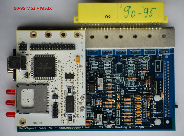
you also need to make sure you have Tachselect to VRIN jumped, and VROUT to TSEL jumped, also seen on the above image.
the signal comes from Tachin, which is the signal provided by your jimstim.
did you put a pull up on that signal like I suggested? a 1K resistor? I use the left hole on r13 (VCC) and jump it to the right hole of R45 (VRIN).
you can see it here:
you also need to make sure you have Tachselect to VRIN jumped, and VROUT to TSEL jumped, also seen on the above image.
Reply
0
0
Thread Starter
Senior Member
Joined: Dec 2007
Posts: 1,467
Total Cats: 132
From: ATL
Check
Nope, just a jimstim.
Check
Not done yet, but will do that tonight
Aha! I'll take a look there and see what happens...
Check
Not sure (working from memory - will check tonite).
Do you have a jimstimx?
Did you jumper the 2nd trigger from the jimstim to the jimstimx or ms3x cam in?
If so look at the composite log. Does it show both green and blue pulse trains?
did you put a pull up on that signal like I suggested? a 1K resistor? I use the left hole on r13 (VCC) and jump it to the right hole of R45 (VRIN).
you also need to make sure you have Tachselect to VRIN jumped, and VROUT to TSEL jumped, also seen on the above image.
Reply
0
0
Thread Starter
Senior Member
Joined: Dec 2007
Posts: 1,467
Total Cats: 132
From: ATL
tonight's discoveries;
- Sending the cam signal to the MS3X; since I don't have a jimstimex, I temporarily soldered a cut jumper wire onto pin 32 of the connector for the MS3X card and the other end of the jumper went to the 2nd trigger pin on the jimstim. (right or wrong?)
- Checking the Tachselect-VRIN jumper (yes)
- Checking the VROUT to Tsel jumper (yes)
- Checking the 1k pull up resistor (yes)
- Datalog results; RPM trace is flat (white on the install of MegaLogViewer that I have w/o any changes), no blue trace (what should that be measuring?), noted that my MAP trace is pretty jittery but I didn't try to investigate a cause (probably because I don't have anything like a syringe connected to it to test).
- Tried to trace the RPM signal from Tachin (thanks Brain) through the schematic. I'm ok with measurements across resistors but when it comes to knowing what, or where, to measure as the signal goes through caps and transistors I'm like a deer in the headlights - stunned and confused. Needless to say, I can see the RPM signal across R45 through R47. After that, I'm completely lost - don't know what I'm looking at, or looking for with the scope. By the time I get to R44, there ain't no signal and I don't know what to make of it.
Bottom line...no RPM in TunerStudio...bummer.
PS - yep, I turned R52 and R56 as prescribed, and then every conceivable way from there - with no effect.
Reply
0
0


Thread Starter
Senior Member
Joined: Dec 2007
Posts: 1,467
Total Cats: 132
From: ATL
No pics right now, but I've got the primary tach jumper in the VR position, and have put the pull-up jumpers for both the primary and secondary tach signals in all three positions (i.e. 5V, 12V and none) with no difference. Other than that, I have the jumper going from the secondary trigger to pin 32 on the MS3X.
There's a jumper on the WBO2 pins and I also have a lead coming from the tach screw-terminal, so that I can look at that signal (that's the orange wire sticking up and going nowhere).
It's "stock" otherwise, built by DIYAutotune.
There's a jumper on the WBO2 pins and I also have a lead coming from the tach screw-terminal, so that I can look at that signal (that's the orange wire sticking up and going nowhere).
It's "stock" otherwise, built by DIYAutotune.
Reply
0
0
Thread Starter
Senior Member
Joined: Dec 2007
Posts: 1,467
Total Cats: 132
From: ATL
nada...nil...zilch...goose eggs...zero...I turned the RPM pots every which-way but loose. I can see the RPM signal from the jimstim on the scope but it's not getting to TS.
I ran it until I got 437 records (yesterday's log was over 1000 records) - not much, but enough to know that "ain't nuttin' hap'nin".
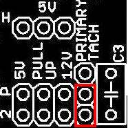
here's a pic of the jimstim all by it's lonesome, and I've attached the datalog.

I'm almost at the point now of "cutting bait" on this...
I ran it until I got 437 records (yesterday's log was over 1000 records) - not much, but enough to know that "ain't nuttin' hap'nin".
here's a pic of the jimstim all by it's lonesome, and I've attached the datalog.
I'm almost at the point now of "cutting bait" on this...
Reply
0
0
The primary tach pin header on your jimstim is jumpered for a vr signal. It should be jumpered for the hall/optical square wave instead.
So, move the jumper to the lower and middle pins of the tach header.
Also, the pullup for the 2nd trigger is unnecessary since the ms3x has a cam pullup at jp7. The crank pullup can be switched to 5v pullup.
So, move the jumper to the lower and middle pins of the tach header.
Also, the pullup for the 2nd trigger is unnecessary since the ms3x has a cam pullup at jp7. The crank pullup can be switched to 5v pullup.
Reply
0
0
Thread Starter
Senior Member
Joined: Dec 2007
Posts: 1,467
Total Cats: 132
From: ATL
I tried it without re-jumpering and still have no tach.
PS - I "discovered" composite logger (embarassed), but there's no tach signal showing there either.
Also, the pullup for the 2nd trigger is unnecessary since the ms3x has a cam pullup at jp7. The crank pullup can be switched to 5v pullup.
I ran across this thread on MSextra where someone was having a "no tach" issue. His situation sounded similar to what I'm experiencing.
Long story short, the suggestion was to check and re-solder Q22 and/or Q23. I did that, with no difference - what I did discover was that I could see the tach signal on the center pin of Q22. The peak voltage was loweer, but the signal was there - is this meaningful information?
Also, on page 2 of the thread, someone else chimed in with voltages on the pins of U7 - so I decided to check those on my board.
Theirs Mine
pin1 - .091 1.31
pin2 - 4.96 4.99
pin3 - 0.55 4.33
pin4 - 0 0
pin5 - 2.55 2.75
pin6 - 1.86 2.76
pin7 - 3.66 2.76
pin8 - 4.96 5.01
When I saw this I thought, "is my U7 fried?"...so, is it? if So, would that have taken out anything else? What else can or should I check?
Last edited by rwyatt365; Oct 26, 2013 at 05:05 PM.
Reply
0
0
The jimstim must be set to square wave to simulate the miata cas regardless of whether the crank input is going to the vr ckt or the opto ckt.
U7 would likely have 0 V dc on pin1/TSEL if it was fried, so yours is probably ok.
Fix your jimstim configuration and keep trying to get full sync using the pots.
On a side note: you have mixed brands for r52 and r56. The gray pot requires about 20 turns CCW while the blue pot takes about 12 CCW and it will click at the end of its travel.
Reply
0
0
Thread Starter
Senior Member
Joined: Dec 2007
Posts: 1,467
Total Cats: 132
From: ATL
Ok, I just spent the last hour looking at the main board schematics and going waaaaaay back to my college electrical engineering classes, and here's what i'm thinking.
I can see the RPM signal at pin 2 on Q22 (the base of the transistor) from R47 (noted in post #29). If Q22 is working, shouldn't I see the RPM signal being "switched" at pin 1 (I haven't checked that - yet)? And, if that's there, wouldn't I see it at R44, and at pin 2 of U7, and the same thing amplified at pin 1 of U7?
I'm trying to understand what I should expect to see at various points on the circuit, and then verify it with measurements on the board.
My operating theory right now (without making measurements) is that Q22 is either shorted, or damaged - sending a flat 5V to one of the OpAmps on U7 which ends up in nothing going to VrOut.
Of course, all of this is coming from an "electronics klutz" with one EE class 30 years ago - so school me...
Reply
0
0
I noticed that the gray pot doesn't "click", so I just turned it CCW until my fingers got tired. Gonna give it another shot this evening.
all you should need is this. you have the pull up on your circuit inside the MS.
Stop digging through schematics and just set it up properly.
what's the red bit of wire on between your RPM pots?
Reply
0
0


