When you click on links to various merchants on this site and make a purchase, this can result in this site earning a commission. Affiliate programs and affiliations include, but are not limited to, the eBay Partner Network.
So inside the MS3 PNP box there is an open pin header labeled and ready for direct connection to USB. Anyone added a USB port to the case? It would be nice to have versus the serial to USB converter.
1. Drill a hole for the cable in the case and insert a rubber grommit to stop the cable sheathing being cut through.
2. Cut the end off an existing serial cable that has Tx, Rx, GND and Pwr wires
3. Thread the cable through the hole you drilled in Step 1
4. Connect the 4 USB pins to the corresponding Serial Port pins (GND=Pin5, Pwr=Pin9, the 2 data pins to Pins2&3 - don't remember which way round so look that up) - I used a Female 4-pin connector for the serial wires.
5. Add zip-ties to both sides of the fascia to stop the cable pulling out, allowing enough for stress relief.
Now you can connect via a USB port.
Like so:
My USB panel socket mounts to a box housed in my glovebox:
Sorry to bring up this semi-dead thread but along the same lines as the OPs question, I was hoping some one could chime in about this, adding a USB connector directly to the MSPNP Pro, there is an unused header with +, - tx and rx, which seems to indicate that its a communications port of some kind.
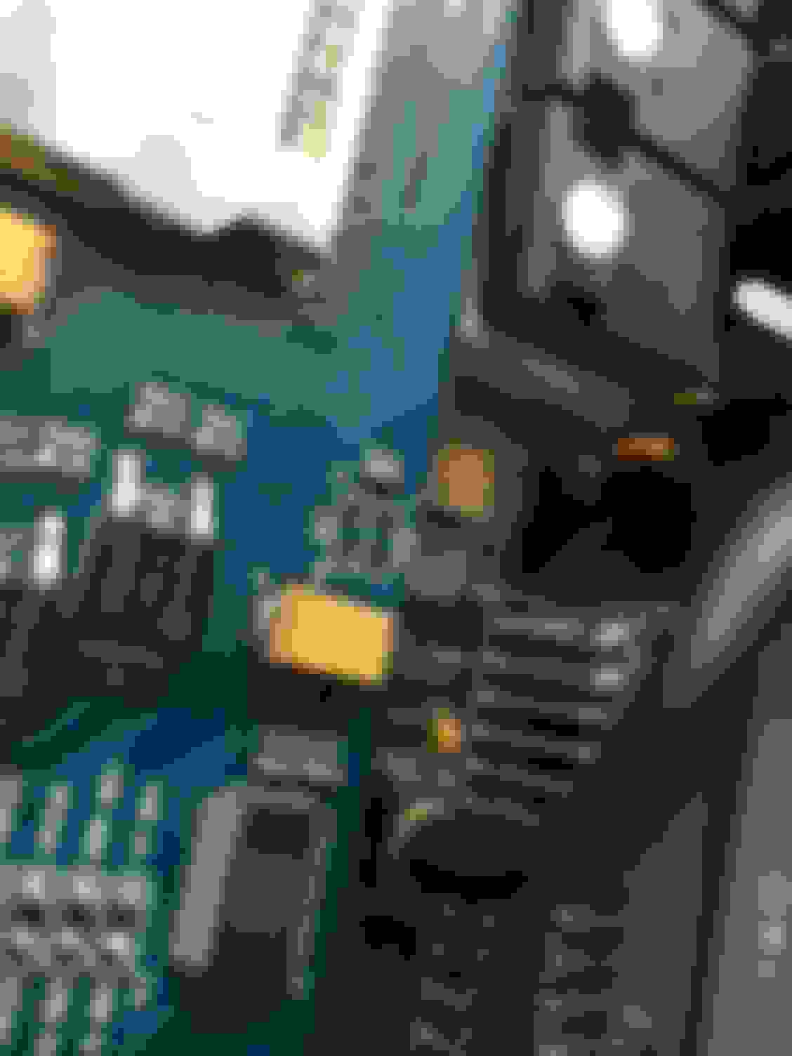
I've added a photo to help illustrate this.
The area I'm talking about is the 'J5' header
This question is an excellent example of why it annoys me that B&G and DIY have stopped publishing schematics for new products. It would be easy to answer the question if they did.
It does not appear to be a USB header. USB uses a differential pair (+/-) for data transmission in both directions; it does not have have discrete TX and RX lines like RS232.
Thanks Joe,
If that's the case, it could be that this is a secondary serial (RS232) header perhaps, and one could if so inclined hard wire a FTDI serial to USB directly to it.
Although it would raise the question of which if either takes precedence.
With space limited in the foot well, I'm looking for a solution to streamline the conga of cables and adapters I'm using.
I have asked DIY why a USB port was not included on the Pro's. It was mostly a positioning choice and making one board module and usable in several different types of cases.
If that's the case, it could be that this is a secondary serial (RS232) header perhaps, and one could if so inclined hard wire a FTDI serial to USB directly to it.
Although it would raise the question of which if either takes precedence.
I honestly cannot answer that. Again, the manufacturer, @DIYAutoTune has chosen not to reveal this information in order to make our lives harder in a bid for some sadistic pleasure which only they can understand.
I can say that in the base MS architecture, there is only one serial port available into the CPU. Typically, a decision is made in the design stage as to whether to present this through a UART driver as RS-232, or into a USB client interface. While I'm sure it's possible, I have never worked on a design in which a single serial channel was multiplexed into different external ports.
If you're really feeling bored, visually trace the TX and RX lines back to their source.
Well I decided to take your advise and take a closer look at the PCB of the MS3Pro module that is the heart of the MS3PNP, started following the traces, although I found it rather difficult with the silkscreen, after poking around a little more, I found something I had shamefully over looked.
There is a native USB pin out, as well as a header pin out, so using an old PC USB expansion connector, I made up a harness for it.
Shuiend is correct about space issues being the reason, at least as far as I can tell, I was going to put a direct USB output onto the case itself, however with the parts I'm using the 21mm cutout would have no chance of fitting, although i think DIY could do it with a breakout board and PCB mounted USB socket.
But as I don't have a mill (yet ) I feel that cutting a rectangular hole wouldn't look acceptably good, and verostrip PCB has no place in an ECU like this.
The cable is mounted on the same end cap as the MAP hose, I used a stainless steel cable glanded rated to IP67, with a cable tie as further strain relief, the cable I used is 4 core individually shield AWG24, thus far I haven't had any problems.
Instead I have mounted the socket in the glovebox along with my WBO2
One thing to keep in mind if anyone else chooses to do this, you need to install the FDTI drivers, Driver Setup EXE, as with my Win10 the auto driver install didn't work, once drivers are install, change "Communication Settings" in TS, still RS232, put change the port.
Here are some photos to show what I've done. (Please excuse the plastic chips in the glove box)
I'd be happy to answer any questions, if anyone is interested in this.
I've got that same header in my ms3pro pnp and the silkscreen text next to it clearly states USB. I'll be trying this out at some point. Anyone want to just try it and report back?
Not sure why my original MS3Pro USB I/O picture no longer works so posting it again:
Yes, it does work, just make sure that you get your USB pins correct (silkscreen print shows the USB pin order).
You only need 4 pins, +ve,GND,D+,D-; 5th pin isn't needed.
I put a rubber grommet in the fascia and zip-ties either side so that the cable is held firmly in place (be sure to allow some slack for stress relief inside the case to prevent the cable from pulling out.
Note: If I were to do it again, I'd drill the hole in the fascia further to the right to give more clearance to the serial port (I only ever use USB and you can't use both serial and USB so it's not a problem but it would make fitting the serial adapter easier).
Got a really strange issue that I'm praying someone has the answer. I grabbed a USB cable and wired it up like the image above. I connected it to the car, go into communication settings and let Tunerstudio find it. Success! Now I have full contact with the ECU. sweet.
But if the car is running, and I plug in that USB, the car goes to crap. It sounds like it is running on 1 cylinder (a lawn mower). Pull the USB plug, goes back to running fine. Bizarre.
BTW - just checked, any USB port (without tunerstudio even on). Meaning, I can instantly go from running well to lawnmower just by inserting the USB. Pull it, back to normal.
I've never tried plugging in the USB WITH the car running.
I'm guessing that it interferes with the normal operation/timing of the ECU which is trying to keep your car running AND establish USB communication at the same time.
The initial handshaking is probably introducing additional delays for normal engine operation.
Does it work fine if the USB is already plugged in before you start the car?
I've never tried plugging in the USB WITH the car running.
I'm guessing that it interferes with the normal operation/timing of the ECU which is trying to keep your car running AND establish USB communication at the same time.
The initial handshaking is probably introducing additional delays for normal engine operation.
I'm not arguing that you're wrong, I'm just puzzled.
Obviously I don't have access to the schematics for the PnP3 (because Bruce Bowling and Al Grippo are evil, fascist monsters who bite the heads of off live kittens), but wouldn't DIY just be using a standard RS-232-USB chip, like a CH340 or an FT2232?
So far as I am aware, the CPU in the MS3 doesn't have anything to do with managing the USB link, it just speaks 232 to an external ASIC, which handles all of that in hardware. Shouldn't be any different from the ECU's point of view from connecting an old-school DB9 RS232 cable while the engine is running.
What changes are happening in the ECU with car engine starter vs. ACC? I'm going to probe some voltages tonight to see if there is a supply issue. Also, is the computer supplying a 5V in addition to the ECU 5V? Some kind of ground loop? Do I we need some kind of regulator or diode?
Can someone else out there try this? I can't be the only one.
Joe, I believe that the MS3 is an embedded device so from a programming perspective, you just have a main loop within which you handle EVERYTHING. If you're lucky you also have interrupt handling.
Attempting to set up communication with TunerStudio via USB or Serial I/O at start-up would be "the norm" so that should be thoroughly ironed out by now.
Attempting to establish communication while controlling the engine too is a different story if the initial "handshaking" takes too much time (eg. a function call takes a long time to respond/return or the implemented code has timing delays built into it for this - this would be bad programming practice). Serial communication has been around a long time and is very simple so it wouldn't surprise me if that's OK but USB communication is more complex.
Think about how long Windows or Linux takes to detect an inserted USB stick. They're REAL operating systems that can run high-end machines with multiple cores and hyperthreading, not simple embedded devices, and even they still take a while to detect them.


 0
0


 ) I feel that cutting a rectangular hole wouldn't look acceptably good, and verostrip PCB has no place in an ECU like this.