
Use dash CEL as a mod warning light with DIYPNP


Thread Starter
Junior Member
iTrader: (1)
Joined: May 2011
Posts: 95
Total Cats: 3
From: South Jersey
Pretty much as it says, I'd like to use the CEL on the Dash as a mode warning light from my diypnp... I was thinking of useing Jean io expander board and setting a bunch of conditions to trigger the CEL to illuminate (battery volts over/under norm), knock, etc...
has anybody else run something like this?
has anybody else run something like this?
Reply
 0
0

0

Thread Starter
Junior Member
iTrader: (1)
Joined: May 2011
Posts: 95
Total Cats: 3
From: South Jersey
right, the regular versions of MS have many more input/ouptuts available... the DIYPNP as youre aware, is limited. I'm already using PA0,PE1,and Flex... so i don't have a lot of options. Using Jean's I/O board would make it much, much easier... but I haven't found anybody using that board, with the DIYPNP, and running the CEL ligth option with it..
(I'm also running sequential injection (-2 ports))
(I'm also running sequential injection (-2 ports))
Reply
0
0

Like NiklasFalk said, I've been doing this for years. The latest CAN-bus enabled version of the Enhanced MS2 has programmable thresholds for many parameters - low RPM, coolant, knock, low/high oil temp, low oil pressure, EGTs.
Reply
0
0

Pretty much as it says, I'd like to use the CEL on the Dash as a mode warning light from my diypnp... I was thinking of useing Jean io expander board and setting a bunch of conditions to trigger the CEL to illuminate (battery volts over/under norm), knock, etc...
has anybody else run something like this?
has anybody else run something like this?
what exactly do you want it to display from? or do you want it to have so many things that can trigger it, when you see it go off you'll just pull your motor and replace to diagnose?
Reply
0
0
Thread Starter
Junior Member
iTrader: (1)
Joined: May 2011
Posts: 95
Total Cats: 3
From: South Jersey
Mainly just want to make sure that board is compatible with the diypnp., I've got some other ideas kicking around.. My wife has a hard time with the light weight flywheel/ MT... Be nice to have a "mommy" switch to engage idle up without turning on the AC, I'd like to port the manifold and put water injection in each runner, and run it like a second set of injectors. A lot of this is just tinker work, once I seriously get time again, I'm going different direction with the car.
Last edited by tuckntruck; Jan 24, 2013 at 05:12 PM.
Reply
0
0


Junior Member
Joined: Jul 2005
Posts: 273
Total Cats: 1
From: Hillsborough, NC
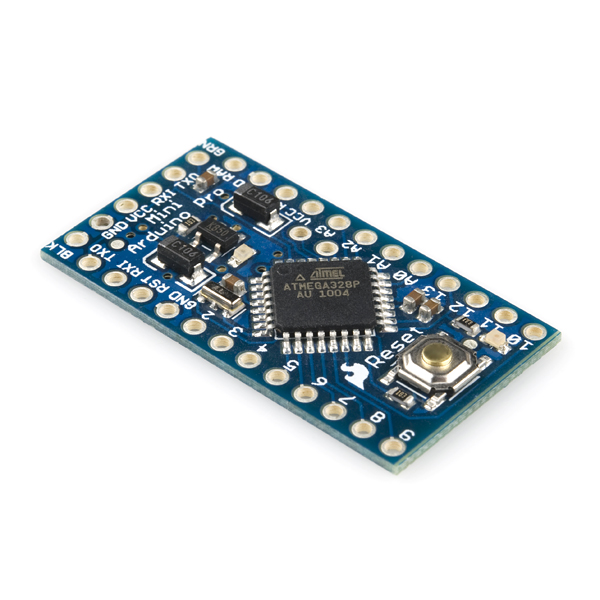
I've been doing this with an arduino pro mini wired to the serial port (internally). It requires programming knowledge though, so it's not the simplest option for most people. It is probably the most flexible though.
Reply
0
0
Junior Member
Joined: Jul 2005
Posts: 273
Total Cats: 1
From: Hillsborough, NC
This is the board I use. It's tiny, and will easily fit in the case.
https://www.sparkfun.com/products/11113
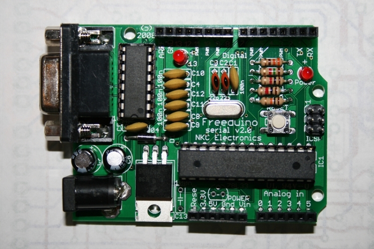
If you're really lazy you could use a regular serial arduino plugged into the external serial port (although you'd have to make a custom serial cable):
Freeduino Serial v2.0 KIT (Arduino Duemilanove Compatible)
https://www.sparkfun.com/products/11113
If you're really lazy you could use a regular serial arduino plugged into the external serial port (although you'd have to make a custom serial cable):
Freeduino Serial v2.0 KIT (Arduino Duemilanove Compatible)
Reply
0
0
Thread Starter
Junior Member
iTrader: (1)
Joined: May 2011
Posts: 95
Total Cats: 3
From: South Jersey
This is the board I use. It's tiny, and will easily fit in the case.
https://www.sparkfun.com/products/11113
If you're really lazy you could use a regular serial arduino plugged into the external serial port (although you'd have to make a custom serial cable):
Freeduino Serial v2.0 KIT (Arduino Duemilanove Compatible)
https://www.sparkfun.com/products/11113
If you're really lazy you could use a regular serial arduino plugged into the external serial port (although you'd have to make a custom serial cable):
Freeduino Serial v2.0 KIT (Arduino Duemilanove Compatible)
Not sure if its too much to ask, but, mind sharing the details of your set up?
Reply
0
0
Junior Member
Joined: Jul 2005
Posts: 273
Total Cats: 1
From: Hillsborough, NC
Cool, could use this set up to make it flash a sequence to troubleshoot faults.. If I'm understanding correctly, your just pulling data off the serial connection, so you could still run it to a Bluetooth adapter for tuning/ shadow dash if desired.
Not sure if its too much to ask, but, mind sharing the details of your set up?
Not sure if its too much to ask, but, mind sharing the details of your set up?
I can share details, but only if you're very serious about doing it. I don't want to spend time on this otherwise. I designed it 3 years ago, so it would take some time to put everything together. And it was originally designed for MS-I/Extra, so me (or someone) would have to update the code to get it to work with the MS-II. I've written code to interface w/ MS-II before, I'd just have to put it together.
And yeah, you should be able to use a bluetooth adapter for tuning, etc, but it will disable the arduino while you're using the serial port for other purposes.
Reply
0
0
Thread Starter
Junior Member
iTrader: (1)
Joined: May 2011
Posts: 95
Total Cats: 3
From: South Jersey
I see another sleepless night spent on Google :-) unfortunately, the last programming class I took was ( in the computer world) a long time ago, and I only paid passing attention to these project micro controllers. Mentioning it creaky got the wheels turning though. If you solder it into the board directly, and leave the serial port open, unless I'm way of base, it should still pass the data right? I would just run the outputs through a different connector.
If its a ton of work, don't worry about it, but I'd deg appreciate a starting point. Ordered a board tonight, so hopeful I can start digging into it soon!
Again, thanks for dropping the idea in the thread, looks like a much better solution then what I was planning
If its a ton of work, don't worry about it, but I'd deg appreciate a starting point. Ordered a board tonight, so hopeful I can start digging into it soon!
Again, thanks for dropping the idea in the thread, looks like a much better solution then what I was planning
Reply
0
0
Junior Member
Joined: Jul 2005
Posts: 273
Total Cats: 1
From: Hillsborough, NC
The serial protocol on the megasquirt is 2-way. The controller (arduino, laptop, phone, whatever) sends a command to request data, and then the megasquirt replys with the data. So if you have two controllers plugged in at the same time, they'll interfere with each other. So I just added a small circuit that monitors the voltage on the serial port line, and ran that to an input on the arduino. When the arduino sees the voltage change, then it goes to sleep.
Which board did you get?
Which board did you get?
Reply
0
0

Fellow Arduino and Megasquirt user (but not together ... yet) I would LOVE to see the code you wrote. Luckily I happen to be MS-1/Extra as well.
If you can remember the schematic you used for the voltage check switching I'd love to see that too, but I'm not sure it would work for me as I was planning on soldering in a BT adapter.
If you can remember the schematic you used for the voltage check switching I'd love to see that too, but I'm not sure it would work for me as I was planning on soldering in a BT adapter.
Reply
0
0
Thread Starter
Junior Member
iTrader: (1)
Joined: May 2011
Posts: 95
Total Cats: 3
From: South Jersey
Fellow Arduino and Megasquirt user (but not together ... yet) I would LOVE to see the code you wrote. Luckily I happen to be MS-1/Extra as well.
If you can remember the schematic you used for the voltage check switching I'd love to see that too, but I'm not sure it would work for me as I was planning on soldering in a BT adapter.
If you can remember the schematic you used for the voltage check switching I'd love to see that too, but I'm not sure it would work for me as I was planning on soldering in a BT adapter.
I got the mini pro..( @ 19 bucks it's worth a shot) well two of them for now, there is a lot of interesting stuff, the done control board with gyro, GPS, baro/temp data and built in data loigging could be interesting as well.
Reply
0
0


