
Looking for BEGI S4 manifold pictures


Thread Starter
Elite Member
iTrader: (15)
Joined: Dec 2007
Posts: 4,847
Total Cats: 27
From: San Antonio, Texas
I am looking for pictures of a BEGI S4 tubular manifold installed in an NB with the turbo in place. In particular I would like a shot showing the clearances around the inlet of the compressor. I need to figure out if I can fit a 4" 90 deg inlet tube, right at the compressor inlet, pointing upwards. I have no PS pump but do have the A/C compressor and the belt tensioner bracket.
Basically I need to determine quickly if I can fit a GT2871 with the 4" inlet anti-surge housing. I posted this at m.n as well.
Basically I need to determine quickly if I can fit a GT2871 with the 4" inlet anti-surge housing. I posted this at m.n as well.
Reply
 0
0

0
Worst case scenario you put a 4" silicone bend on the compressor inlet and then put your pipe. It should fit fine though IMO. I can only assume the S4 mani keeps the turbine centered relative to the length of the engine. (IE-doesn't move the assembly forward or backwards. My cast mani keeps it centered for example.) I'd either do a 4" bend or perhaps a 4" to 3" transition and then a 3" bend.
Reply
0
0
Thread Starter
Elite Member
iTrader: (15)
Joined: Dec 2007
Posts: 4,847
Total Cats: 27
From: San Antonio, Texas
- It keeps it centered on the engine front to back from what I can tell.
- It does move the turbine flange downward about 6 inches or so compared to the BEGI cast. Plus the turbine flange faces downward.
- Side-to-side I do not know.
I want to be sure I am not headed for Fail-ville before I pull the trigger on this turbo since it will just waste time if I have to swap out the compressor housing for the 3" version. I am hoping someone with a S4 took a bunch of installation pictures.
Reply
0
0

- It keeps it centered on the engine front to back from what I can tell.
- It does move the turbine flange downward about 6 inches or so compared to the BEGI cast. Plus the turbine flange faces downward.
- Side-to-side I do not know.
I want to be sure I am not headed for Fail-ville before I pull the trigger on this turbo since it will just waste time if I have to swap out the compressor housing for the 3" version. I am hoping someone with a S4 took a bunch of installation pictures.
- It does move the turbine flange downward about 6 inches or so compared to the BEGI cast. Plus the turbine flange faces downward.
- Side-to-side I do not know.
I want to be sure I am not headed for Fail-ville before I pull the trigger on this turbo since it will just waste time if I have to swap out the compressor housing for the 3" version. I am hoping someone with a S4 took a bunch of installation pictures.
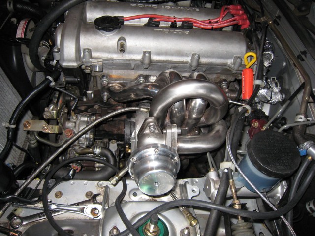
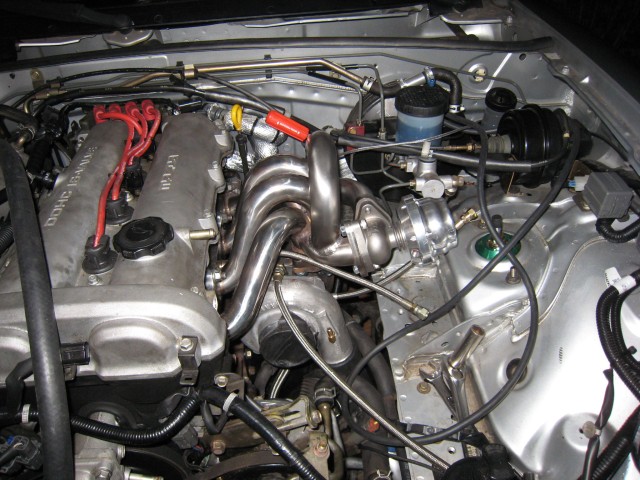
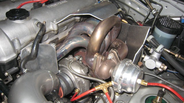
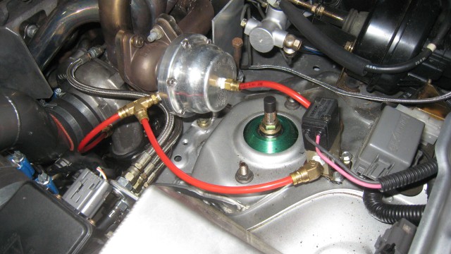
It is really F'n tight in there, moreso when you have PS.
Here are the best I have.
Reply
0
0
Thread Starter
Elite Member
iTrader: (15)
Joined: Dec 2007
Posts: 4,847
Total Cats: 27
From: San Antonio, Texas
Excellent, thanks PSchmidt, thanks Steph. Which turbos are those?
It looks like there is plenty of room to clear the shelf.
It also looks like even the bottom of the compressor housing is above or at the top of the a/c compressor, plus it looks like they do not overlap by a couple of inches.
The way the #1 runner is routed there will be room for the upturned inlet elbow, though a heat shield might be a good idea. I am planning on fabricating one anyway.
It is definitely a tight fit with the PS pump so I am glad I depowered the rack while I had the engine out.
Based on those pictures I think it will fit for sure with the 3" inlet and probably the 4".
Steph you have e-mail.
Last edited by ZX-Tex; Feb 23, 2009 at 06:01 PM.
Reply
0
0
Thread Starter
Elite Member
iTrader: (15)
Joined: Dec 2007
Posts: 4,847
Total Cats: 27
From: San Antonio, Texas
Actually the S4 manifold was already in the plan. That is why I sold the cast manifold with the turbo and the DP.
From talking to Corky, in their experience, the S4 will allow one to go up '1-1.5 sizes' on the turbo with about the same low-end spool characteristics (when compared to the cast manifold). So the idea is, bigger turbo (up about 'two sizes') but retain about the same low-end spool behavior. Plus of course it will flow better than the cast manifold. And, the full 3" Enthuza exhaust I'm adding will help spool and flow too.
No EWG, but I will be using the separated gases manifold.
The up two sizes is a loose description but you get the idea. GT2554, GT2560, GT2860, GT2871, etc.
Reply
0
0
Thread Starter
Elite Member
iTrader: (15)
Joined: Dec 2007
Posts: 4,847
Total Cats: 27
From: San Antonio, Texas
Well, I could lose even more money 
Not to be argumentative, but I am not so sure it is going to make a huge difference. The separated gases pipe will keep the wastegate gases from being reintroduced right at the turbine exit, so that will help with turbine flow like a EWG would. I would not vent the dump tube to atmosphere with a EWG since I am not into the way it sounds, so no flow advantage there since IWG or EWG I'll be reintroducing the WG flow to the DP. If I do not have boost creep problems then I would not need the extra flow from the EWG either.
I would need a pretty compelling reason at this point to go with a EWG but I'm open to discussion here.
Reply
0
0
You can stick with the current plans. Upgrading to external if you have boost management issues wouldn't be that big of a deal.
BEGI could modify the manifold easily and build you a new downpipe that had the WG reintroduced and blocked off the WG port in the turbine housing. No worries.
BEGI could modify the manifold easily and build you a new downpipe that had the WG reintroduced and blocked off the WG port in the turbine housing. No worries.
Reply
0
0
Well, I could lose even more money
Not to be argumentative, but I am not so sure it is going to make a huge difference. The separated gases pipe will keep the wastegate gases from being reintroduced right at the turbine exit, so that will help with turbine flow like a EWG would. I would not vent the dump tube to atmosphere with a EWG since I am not into the way it sounds, so no flow advantage there since IWG or EWG I'll be reintroducing the WG flow to the DP. If I do not have boost creep problems then I would not need the extra flow from the EWG either.
I would need a pretty compelling reason at this point to go with a EWG but I'm open to discussion here.
A dual port EWG can be setup with an MBC such that it stays 100% pinned shut until you reach target boost/the MBC opens. IE-if you run 15.00 PSI and your MBC cracks open at 14.7. Then when you're building boost and get to 14.6, the wastegate is still pinned shut. Then when the MBC opens an air spring forms on the other side of the diagphram, and it instantly opens.
EWG's are better at preventing overshoot when reaching target boost and also better at maintaining target boost where IWG's are known to creep at some RPMs or completely fail to hold target boost when using a large turbo at low boost with a highly efficient system (ding ding ding?).
Reply
0
0

Former Vendor
Joined: Jun 2006
Posts: 1,337
Total Cats: -100
From: Bell Tuning & Performance
Corky is working on a good solution to adding the Ext. WG to the S4 manifold. The two previous designs do not work well enough. It is being built now, but has not been tested.
Stephanie
Stephanie
Reply
0
0
Any possibility for the people who have manifolds with the previous designs to update to the new version? I'd even be a guinea pig if you need testers.
Reply
0
0

 I have barricaded the house. The Brown Santa will not escape!
Last edited by MazDilla; Feb 24, 2009 at 11:54 AM. Reason: Wink wink, nudge nudge, know what I mean? ;)
Reply
0
0
Former Vendor
Joined: Jun 2006
Posts: 1,337
Total Cats: -100
From: Bell Tuning & Performance
I would prefer to send you a part that works better than what you already have.
Stephanie
Reply
0
0


