
Aerodynamic Discussion Thread
 01-31-2015, 06:45 PM
#662
ʎpunq qoq

Join Date: Jan 2014
Location: Western Australia
Posts: 604
Total Cats: 201
It looks to me like the cell size for the simulation might not be small enough to pick up the thin walls of the diffuser. I can't see how that air could flow across the back like that.

Reply
 0
0

0
 01-31-2015, 07:58 PM
#664
ʎpunq qoq
Join Date: Jan 2014
Location: Western Australia
Posts: 604
Total Cats: 201
Still that flow looks very wrong for some reason. If the air was really flowing past the verticals then you would surely see very high pressure zones under each. Maybe there is a large gap to the ground where the air can cross but the whole point of those fins is to prevent that happening. If the sim is correct why have the fins at all?
Reply
0
0
01-31-2015, 09:11 PM
#665
What I was pointing as is that, thats a pretty nice solid model. Its just surprising someone is able to make something that nice on the model side but then not do something fairly simple like that, or even fail to catch it when just looking at the results. It really does look like the sims are ignoring that the strakes even exist.
Theres some other oddities, like how the flow separated on the inside of the tires without significant turbulence. And there's also quite a few surface errors as well which certainly arent helping. Looking closer I dont think this is a solid model, I think someone scanned this in.
Theres some other oddities, like how the flow separated on the inside of the tires without significant turbulence. And there's also quite a few surface errors as well which certainly arent helping. Looking closer I dont think this is a solid model, I think someone scanned this in.
Reply
0
0
01-31-2015, 11:07 PM
#666
ʎpunq qoq
Join Date: Jan 2014
Location: Western Australia
Posts: 604
Total Cats: 201
What I was pointing as is that, thats a pretty nice solid model. Its just surprising someone is able to make something that nice on the model side but then not do something fairly simple like that, or even fail to catch it when just looking at the results. It really does look like the sims are ignoring that the strakes even exist.
Theres some other oddities, like how the flow separated on the inside of the tires without significant turbulence. And there's also quite a few surface errors as well which certainly arent helping. Looking closer I dont think this is a solid model, I think someone scanned this in.
Theres some other oddities, like how the flow separated on the inside of the tires without significant turbulence. And there's also quite a few surface errors as well which certainly arent helping. Looking closer I dont think this is a solid model, I think someone scanned this in.
It looks ok but I know from my sims you sometimes need to bulk up the thin walls up to bigger than your cell size otherwise with the size of the cells let the air through like they are permeable.
Reply
0
0
02-11-2015, 07:21 AM
#667
Senior Member

Join Date: Jul 2014
Location: Canberra, sort of
Posts: 1,090
Total Cats: 184

Bearing in mind the data reservations above, should I be pencilling a concave, or a convex, shape?
Reply
0
0
02-22-2015, 08:13 AM
#668
Senior Member

Join Date: Dec 2012
Location: Charlotte, NC
Posts: 538
Total Cats: 64
Saw the Silver-Car at the MSX yesterday. Was surprised to see these roof rails feeding the rear wing:
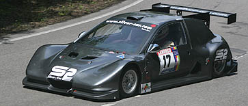
The car has a DTM type flat bottom/rear diffuser and fiberglass skirts in addition to the wing. One of the tech guys said they saw significant gains with those roof fins during their wind tunnel testing, and they made it on to the final version of the production car.
That thing weighs 900 lbs and has 200HP...
Reply
0
0
02-22-2015, 08:20 AM
#669
Senior Member
Thread Starter

Join Date: Oct 2011
Location: The Race Track & St Pete FL
Posts: 638
Total Cats: 57
Saw the Silver-Car at the MSX yesterday. Was surprised to see these roof rails feeding the rear wing:
The car has a DTM type flat bottom/rear diffuser and fiberglass skirts in addition to the wing. One of the tech guys said they saw significant gains with those roof fins during their wind tunnel testing, and they made it on to the final version of the production car.
That thing weighs 900 lbs and has 200HP...
Reply
0
0
02-22-2015, 10:27 AM
#670
Senior Member
Join Date: Dec 2012
Location: Charlotte, NC
Posts: 538
Total Cats: 64
One the K1, those double as a swan neck wing mount. In the Silver-Car, the wing mount is separate. These are only for guiding airflow.
That car is rear engine and has a firewall behind the driver, so visibility is moot anyways in this case. It also doesn't extend all the way down the rear body work, it was about 4" deep after the immediate roof line. I understand it can act as a safety feature if sliding sideways, but I wonder if extending them to the leading edge of the wing provides benefits similar to spill plates on a splitter.
That car is rear engine and has a firewall behind the driver, so visibility is moot anyways in this case. It also doesn't extend all the way down the rear body work, it was about 4" deep after the immediate roof line. I understand it can act as a safety feature if sliding sideways, but I wonder if extending them to the leading edge of the wing provides benefits similar to spill plates on a splitter.
Reply
0
0
02-22-2015, 11:10 AM
#671

Looking at this picture, the roof fins make sense. The roof has a nice gentle slope to "put the air back together" and feed air to the wing, but I'm sure the air gets super dirty once it drops over the edge onto the rear hatch window. The roof fins should help keep the air from the sides of the car from spilling in. Seems like just raising the wing up into cleaner air would have been more effective, though.

Reply
0
0
02-23-2015, 10:07 AM
#672

many racing bodies don't allow the wing to be higher then the roof.
__________________
OG Racing
Your Source For Motorsports Safety Equipment
WWW.OGRACING.COM
800.934.9112
703.430.3303
info@ogracing.com
OG Racing
Your Source For Motorsports Safety Equipment
WWW.OGRACING.COM
800.934.9112
703.430.3303
info@ogracing.com
Reply
0
0
02-24-2015, 08:50 AM
#674
i got the 200. i am about to raise it to the roof line.
__________________
OG Racing
Your Source For Motorsports Safety Equipment
WWW.OGRACING.COM
800.934.9112
703.430.3303
info@ogracing.com
OG Racing
Your Source For Motorsports Safety Equipment
WWW.OGRACING.COM
800.934.9112
703.430.3303
info@ogracing.com
Reply
0
0
03-23-2015, 05:48 PM
#675
Senior Member
Thread Starter
Join Date: Oct 2011
Location: The Race Track & St Pete FL
Posts: 638
Total Cats: 57
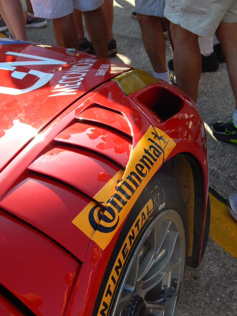
So I took some pics at 12 Hours of Sebring this past Saturday
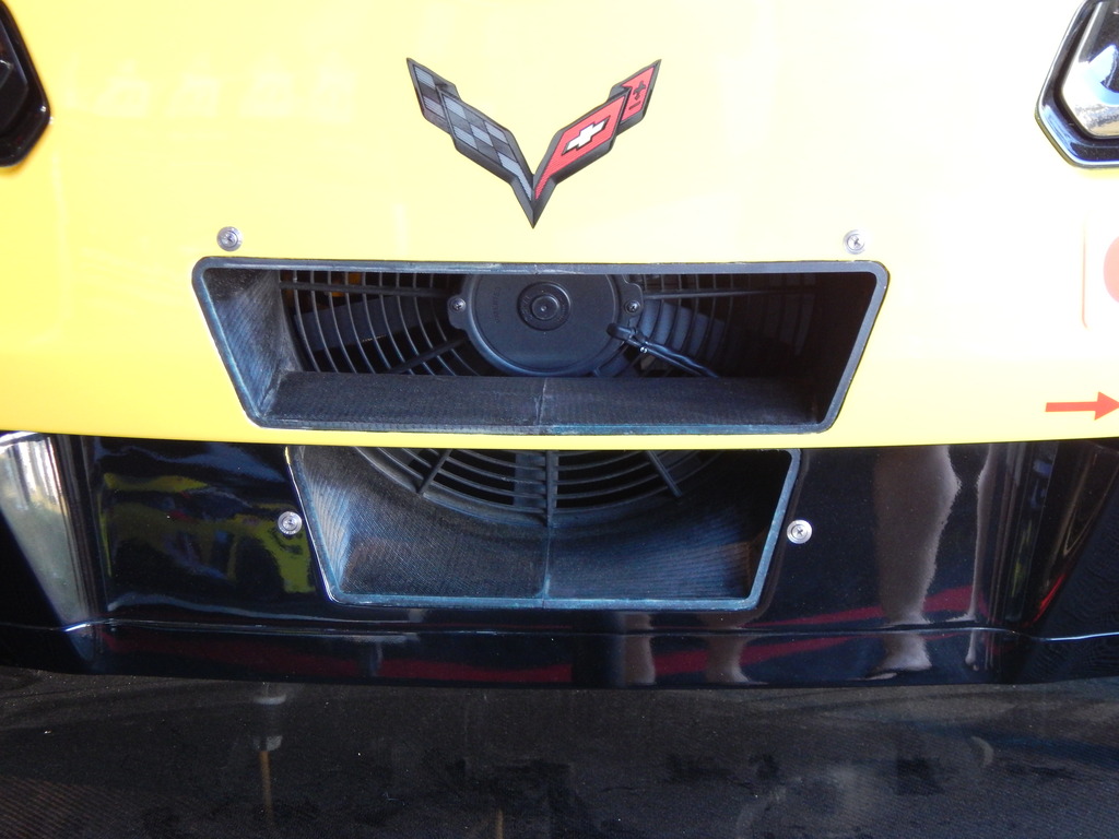
C7R rear bumper
This I thought was a little weird, a plug hanging with a yellow extension cord
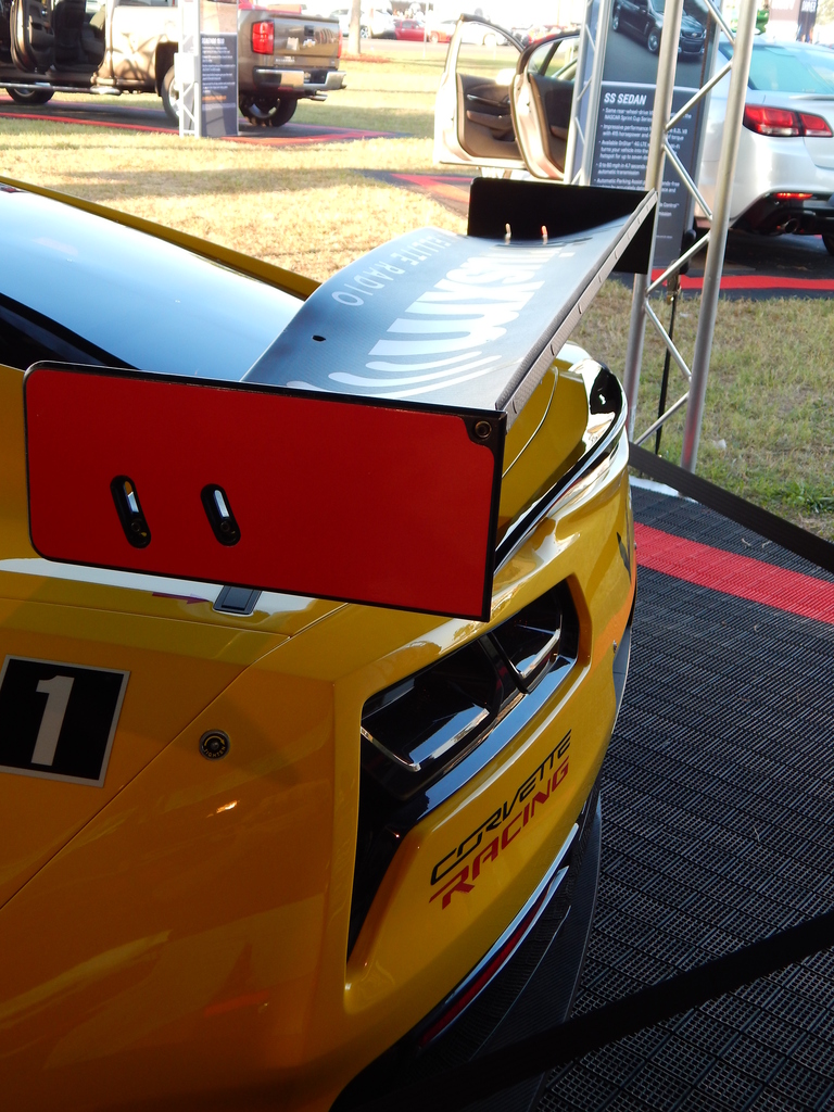
C7R rear wing of course
Ferrari Front fender
Viper's large front wheel well vents

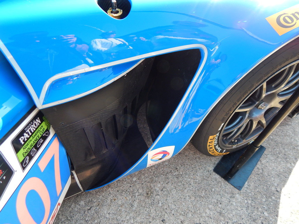
Aston Martin #007 Front wheel well vents

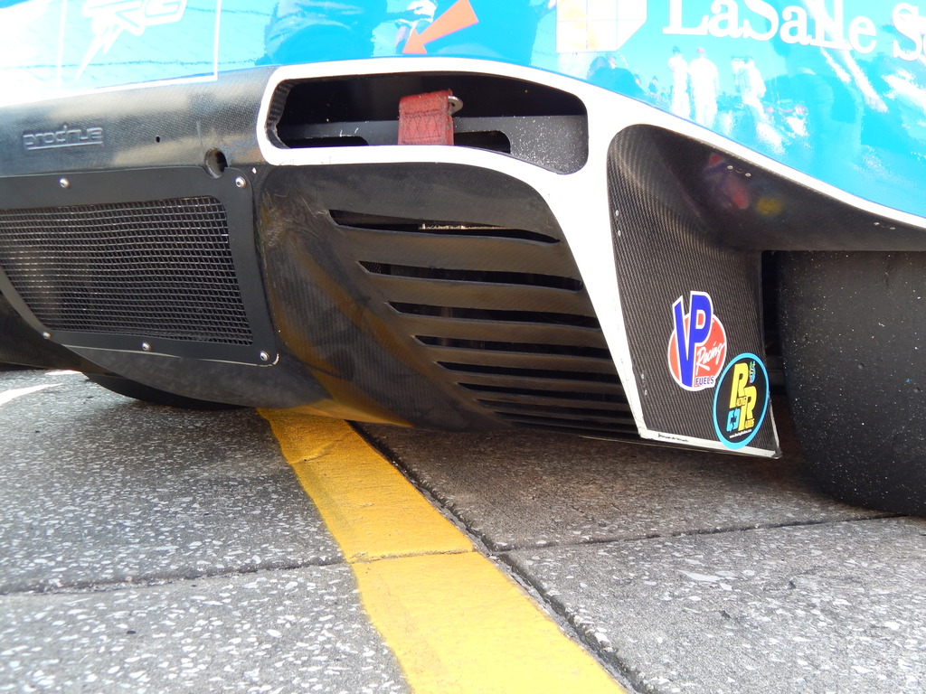
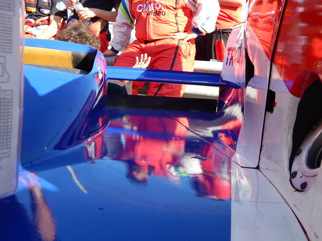
Aston Martin #007 Rear Diffuser
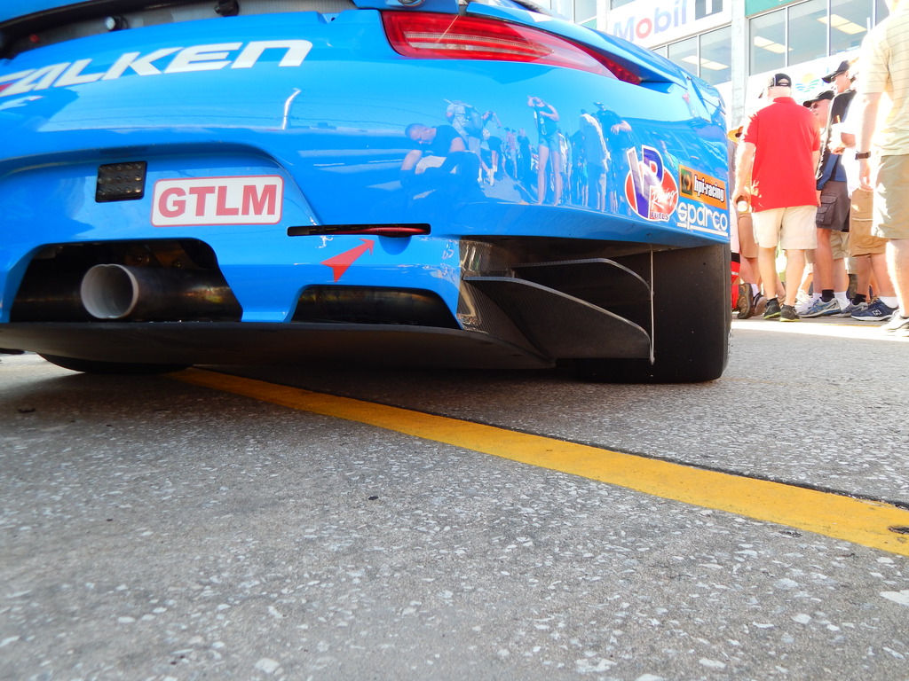
Falken Tire 911 Porsche Rear Diffuser
Ferrari 458 Front Splitter

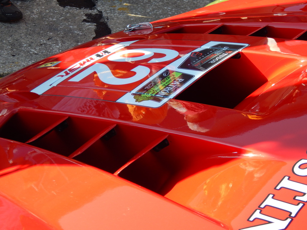
Ferrari 458 Rear Duct
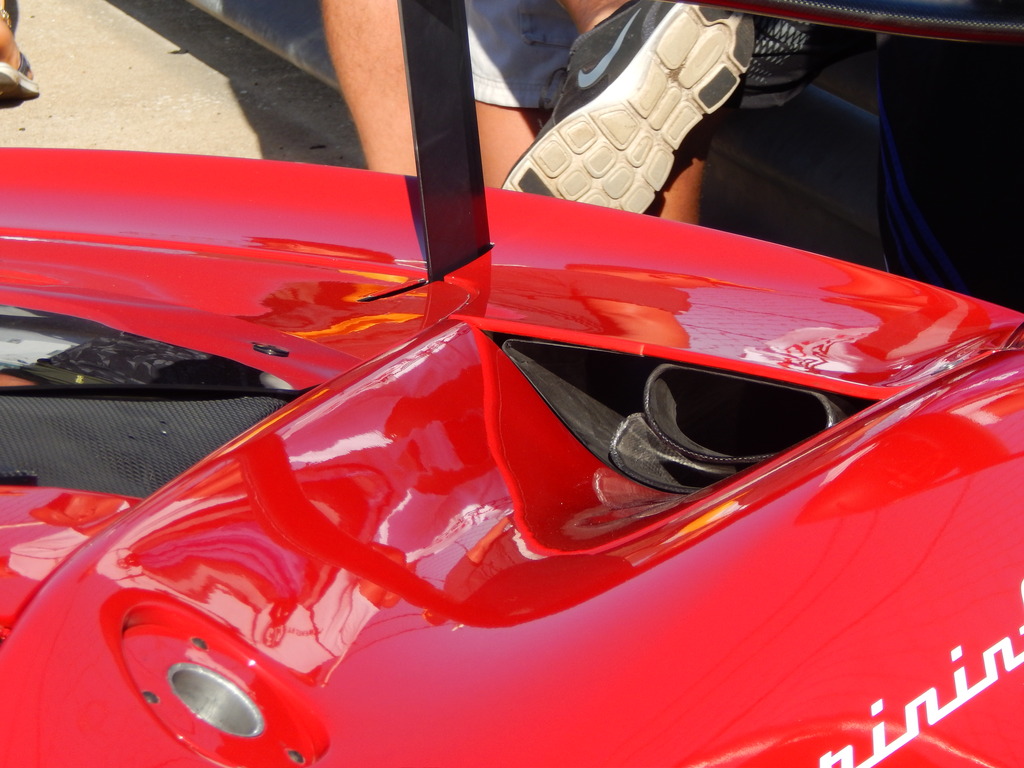
Ferrari 458 Rear Wing with Step
Ferrari 458 Front Hood
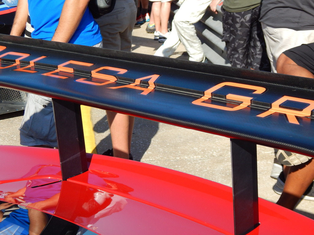
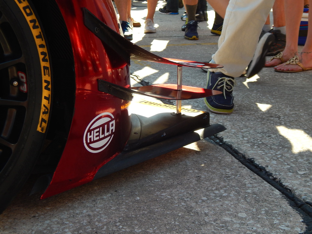
Delta Wing's wing and about 1".5 -2" gurney flap right below the rear wing
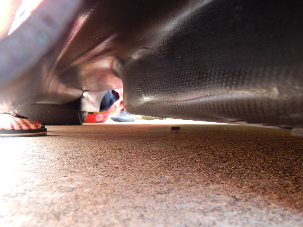
Delta Wing Underbody channels and no those are not my feet
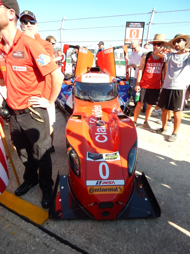
Delta Wing Front
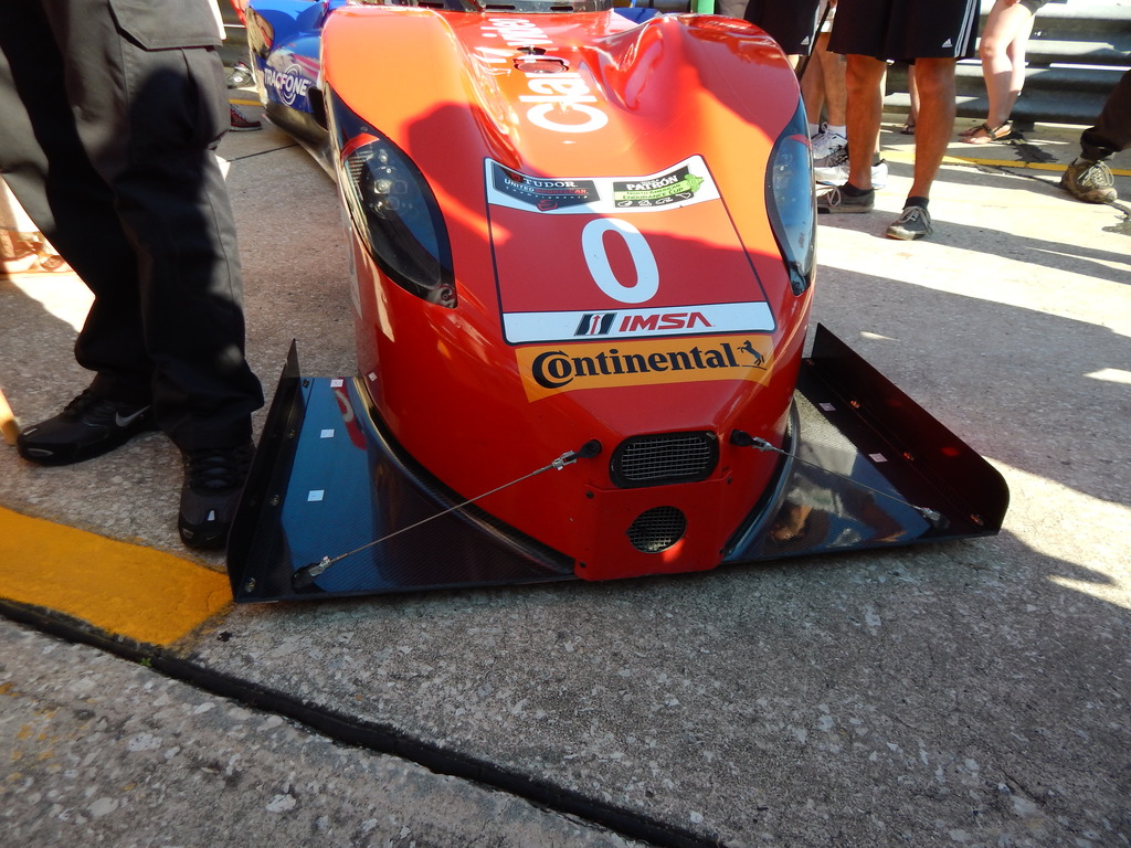
Delta Wing Front Splitter
C7R rear bumper

This I thought was a little weird, a plug hanging with a yellow extension cord

C7R rear wing of course

Ferrari Front fender

Viper's large front wheel well vents

Aston Martin #007 Front wheel well vents


Aston Martin #007 Rear Diffuser

Falken Tire 911 Porsche Rear Diffuser

Ferrari 458 Front Splitter

Ferrari 458 Rear Duct

Ferrari 458 Rear Wing with Step

Ferrari 458 Front Hood

Delta Wing's wing and about 1".5 -2" gurney flap right below the rear wing

Delta Wing Underbody channels and no those are not my feet

Delta Wing Front

Delta Wing Front Splitter

Last edited by 1993ka24det; 03-25-2015 at 03:35 PM.
Reply
0
0
03-23-2015, 05:48 PM
#676
Senior Member
Thread Starter
Join Date: Oct 2011
Location: The Race Track & St Pete FL
Posts: 638
Total Cats: 57
Mazda Skyactive Diesel Dive Planes
Mazda Skyactive Diesel Side

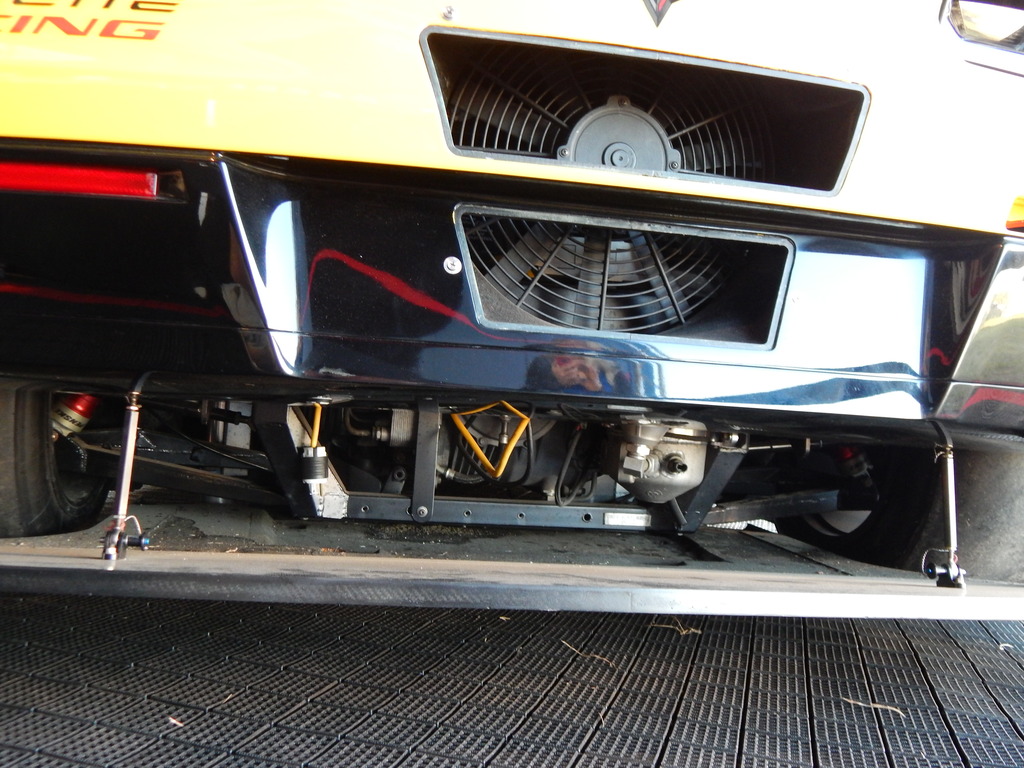
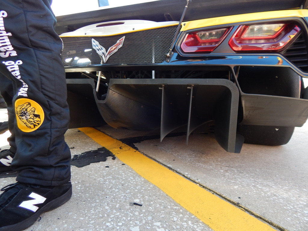
Prototype Corvette powered Rear Diffuser

Mazda Skyactive Diesel Side

Prototype Corvette powered Rear Diffuser

Last edited by 1993ka24det; 03-23-2015 at 06:03 PM.
Reply
0
0
 03-25-2015, 09:13 AM
#679
it's interesting to see that the ferrari and DW almost don't want the high pressure air in the center of the splitter. the DW is flush with the front of the bumper, and the ferrari have big gaps. wonder why?
__________________
OG Racing
Your Source For Motorsports Safety Equipment
WWW.OGRACING.COM
800.934.9112
703.430.3303
info@ogracing.com
OG Racing
Your Source For Motorsports Safety Equipment
WWW.OGRACING.COM
800.934.9112
703.430.3303
info@ogracing.com
Reply
0
0


