

Miata cooling system thread


That's very nice of you to say, that's awesome! What video was it? I've got one from the turbo days, and a few with the Whipple.
Reply
 0
0

0


There is a spray for cleaning home A/C coils at Lowe's.
Taz, you said you didn't seal the bumper mouth to the sides of the radiator. You've got to start there.
Taz, you said you didn't seal the bumper mouth to the sides of the radiator. You've got to start there.
Reply
0
0

Junior Member
Joined: Sep 2014
Posts: 216
Total Cats: 2
From: Portland (left coast)
Best set-up photo I have seen that might be within reach for my non-engineering *** is this one:
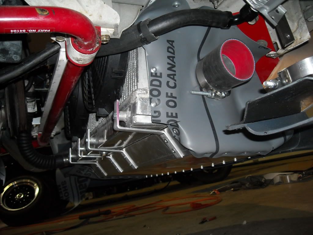
From this thread: https://www.miataturbo.net/race-prep...g-ideas-69274/
Reply
0
0

Source: I work in military maintenance manuals/ procedures. There are loads of regulations/ specs regarding galvanic corrosion in dissimilar metals.
I have a little chunk of zinc safety wired to my radiator cap. It serves the same purpose as the Trackspeed cap anode, it's just not as secure.
Reply
0
0
So is zinc wire the best material, or would magnesium wire work better, for the sacrificial anode?
I remember in chemistry burning the magnesium ribbon, so maybe magnesium wire wouldn't be the best choice?
Thanks
I remember in chemistry burning the magnesium ribbon, so maybe magnesium wire wouldn't be the best choice?
Thanks
Reply
0
0

^^ This guy gets it 
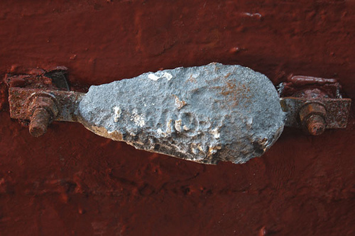
Zinc "should" be more reactive than the aluminum and thus the corrosion will attack it first rather than the radiator. Boats almost exclusively use aluminum outboard housings and sometimes props, and all are equipped with a large zinc anode exposed to the water somewhere in the system.
They usually end up looking like this eventually:
Check it: https://en.wikipedia.org/wiki/Galvanic_anode
Reply
0
0
 good one!
Junior Member
Joined: Sep 2014
Posts: 216
Total Cats: 2
From: Portland (left coast)
Once I got the bumper off I can clearly see why people ditch the A/C. At least mine was clean. I would like to see temp. number before and after the A/C is removed.
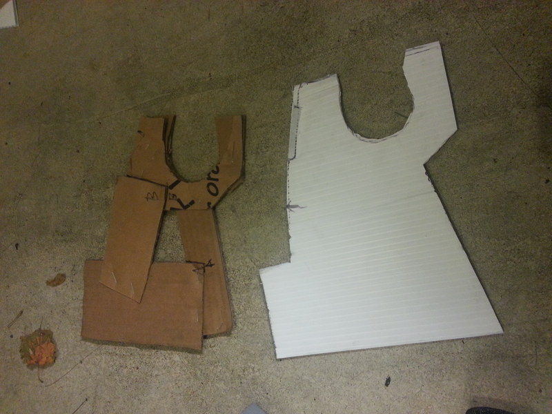
Anyhow, the space to fill/block is annoying. I started by piecing together small cardboard shapes that I worked on trimming, then slowly built into a shape. That was then transferred to a solid shape which was test fitted and modified (final version not shown).
From the passenger side, the piece fills the space well. Single strip of tape and a zip-tie (hidden in photo by IC pipe) to seal and pull the part out towards the wheel:
From da top! looking down, pass. side.
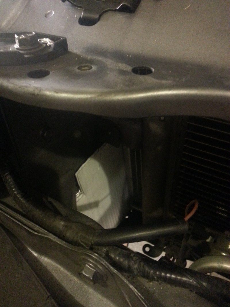
This is ugly, I know, but sealed. I ran hot water pipe foam cut to fit and slid it down the long space between the radiator and body. There is a funky shaped opening at the upper, outter point of the radiator and foar helped fill this space. I think the foam may have worked fine, but the tape helps ensure the foam stays put.
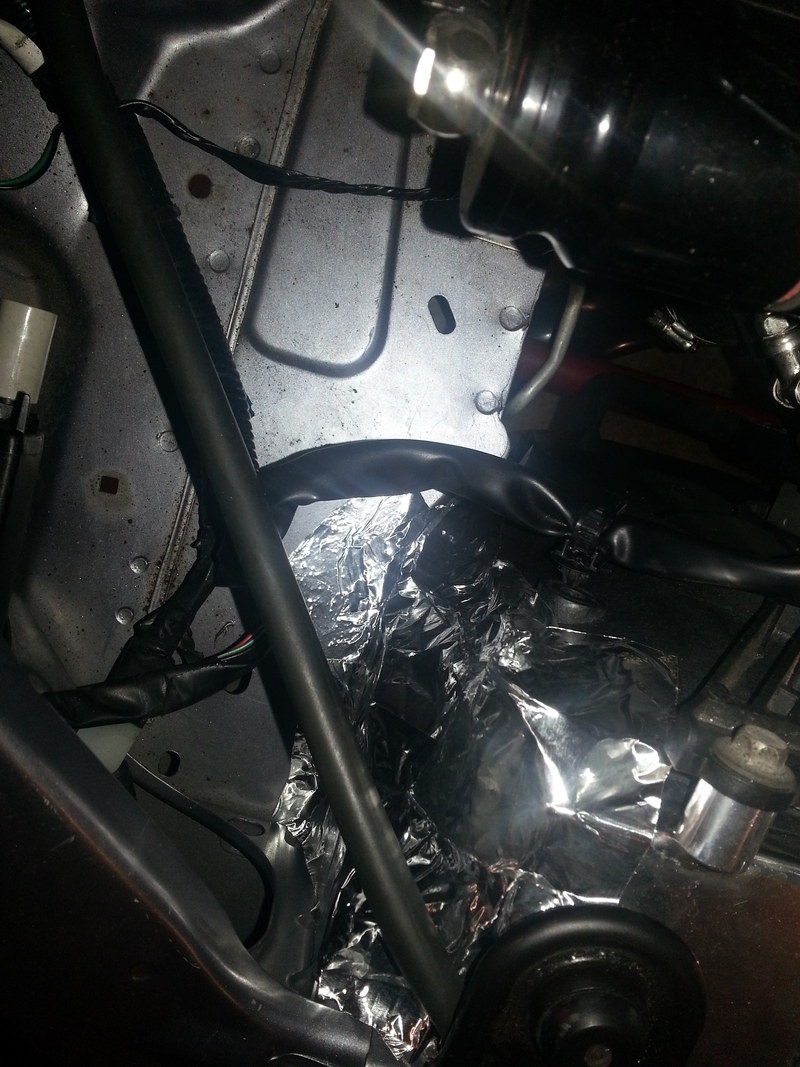
Once the bumper was put back I could see where I can make this even better and drop the duct piece down lower so it makes contact with the OE under-tray. Also, I think I can extend the forward arms of the part to actually contact the front of the pumper creating more of a full channel.
I drive The Ridge in WA in three weeks so I will see how it does.
Anyhow, the space to fill/block is annoying. I started by piecing together small cardboard shapes that I worked on trimming, then slowly built into a shape. That was then transferred to a solid shape which was test fitted and modified (final version not shown).
From the passenger side, the piece fills the space well. Single strip of tape and a zip-tie (hidden in photo by IC pipe) to seal and pull the part out towards the wheel:
From da top! looking down, pass. side.
This is ugly, I know, but sealed. I ran hot water pipe foam cut to fit and slid it down the long space between the radiator and body. There is a funky shaped opening at the upper, outter point of the radiator and foar helped fill this space. I think the foam may have worked fine, but the tape helps ensure the foam stays put.
Once the bumper was put back I could see where I can make this even better and drop the duct piece down lower so it makes contact with the OE under-tray. Also, I think I can extend the forward arms of the part to actually contact the front of the pumper creating more of a full channel.
I drive The Ridge in WA in three weeks so I will see how it does.
Reply
0
0
People who like to make more work for themselves than necessary may enjoy this setup. That said, it works really well. I have yet to find a situation where it's not been more than adequate, and that includes everything from hot track days to traffic jams at 100+ degrees. Yes, my engine situation is a little different but this setup still holds up to close to 400whp.
Anyway, I chose to package my radiator like this because good ducting, on both sides, is easy to implement. It plays nicely with my air intake. The mass of the radiator is also kept relatively low and far back. The fans are able to uniformly draw air through the core which makes their job easier. This setup also uses an electric water pump with no thermostat. The temperature is regulated by varying the water pump speed.
Anyway, pictures...


The keen observer will notice that this radiator is different from the one shown above. This one ended up leaking so I substituted it with a custom one that's a bit larger.


Anyway, I chose to package my radiator like this because good ducting, on both sides, is easy to implement. It plays nicely with my air intake. The mass of the radiator is also kept relatively low and far back. The fans are able to uniformly draw air through the core which makes their job easier. This setup also uses an electric water pump with no thermostat. The temperature is regulated by varying the water pump speed.
Anyway, pictures...
The keen observer will notice that this radiator is different from the one shown above. This one ended up leaking so I substituted it with a custom one that's a bit larger.
Reply
0
0

Second: Interesting data on oil cooler placement and hood venting here:
Project S2000: Part 23. Testing Air Temps Through Coolers and Vents
Project S2000: Part 23. Testing Air Temps Through Coolers and Vents
Reply
0
0
I've actually sold that set and gone with something totally different. I don't have any good pictures of the new ones yet but they're adaptive and work incredibly well. If you check my build thread in about a week or so I'll probably have an update.
Reply
0
0
Second: Interesting data on oil cooler placement and hood venting here:
Project S2000: Part 23. Testing Air Temps Through Coolers and Vents
Project S2000: Part 23. Testing Air Temps Through Coolers and Vents
Reply
0
0
I can't think of any reason why you would keep the exchangers separate in this case. I guess you'll transfer a little of the heat from the oil cooler to the water, but I would see that as a benefit, not a deficit.
EDIT: You might see some chafing between the heat exchangers, which would be a serious problem over time....
Reply
0
0
Doing a bit of a google search, the air gaps between exhangers (minimum 1/2") is recommended to promote air flow. It gives the air space to move and realign to the different fin configurations used in the respective heat exchangers. Kind of the same theory as using a bell mouth rather than a straight cut at an air inlet. That makes intuitive sense, but I don't have any data to back it up other than that the OEMs do it when they add coolers for HD towing packages, AC options, etc.
And, of course, chafing is not cool (pun intended).
And, of course, chafing is not cool (pun intended).
Reply
0
0

Newb
Joined: Sep 2015
Posts: 3
Total Cats: 4
This is my first post, so please be gentle. I am active over at Mazda-speed, but have only lurked over here. There has been some talk recently about radiator ducting and the MSM. I have just completed this project and thought I would share how I did it. I am running the FM crossflow radiator, Spal fans and oil cooler.
First a little history-my wife and I both drive and instruct at HPDE/DE's- no wheel to wheel racing. We mainly drive with the PCA and our home track is Roebling Road in Savannah, GA. This car is a duel purpose car and acts as both a date night car and a track toy. Due to the nature of it being duel purpose, many compromises have had to be made. No parts have been removed and no body panels have been harmed in its evolution.
The car goes from date night clothing....
to it's track clothing.
The car's cooling system has been working pretty well except for the June events, where ambient temps approach 100 degrees. When my wife and I are both instructing, the car sees approximately (10) 20 minute sessions each day at a DE. It is also common for our run groups to be back to back, so often times, the car basically sees 40 minutes on track with a short 3 or so minute break for us to swap drivers.
The ducting is basically made up up 5 main pieces.
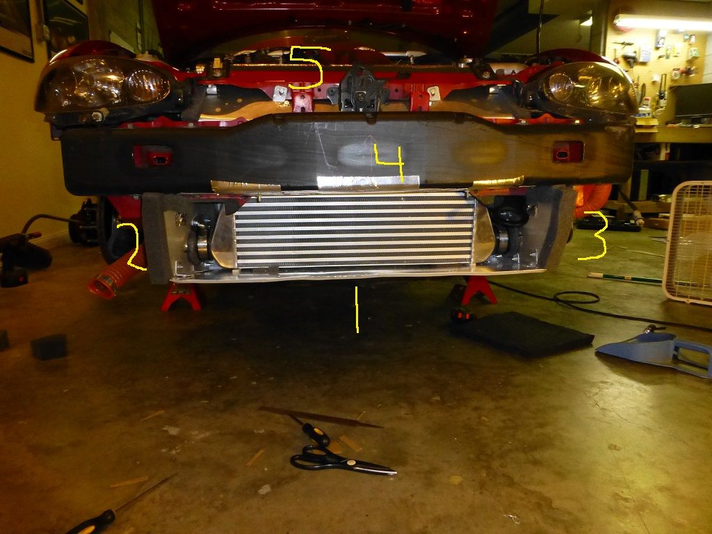
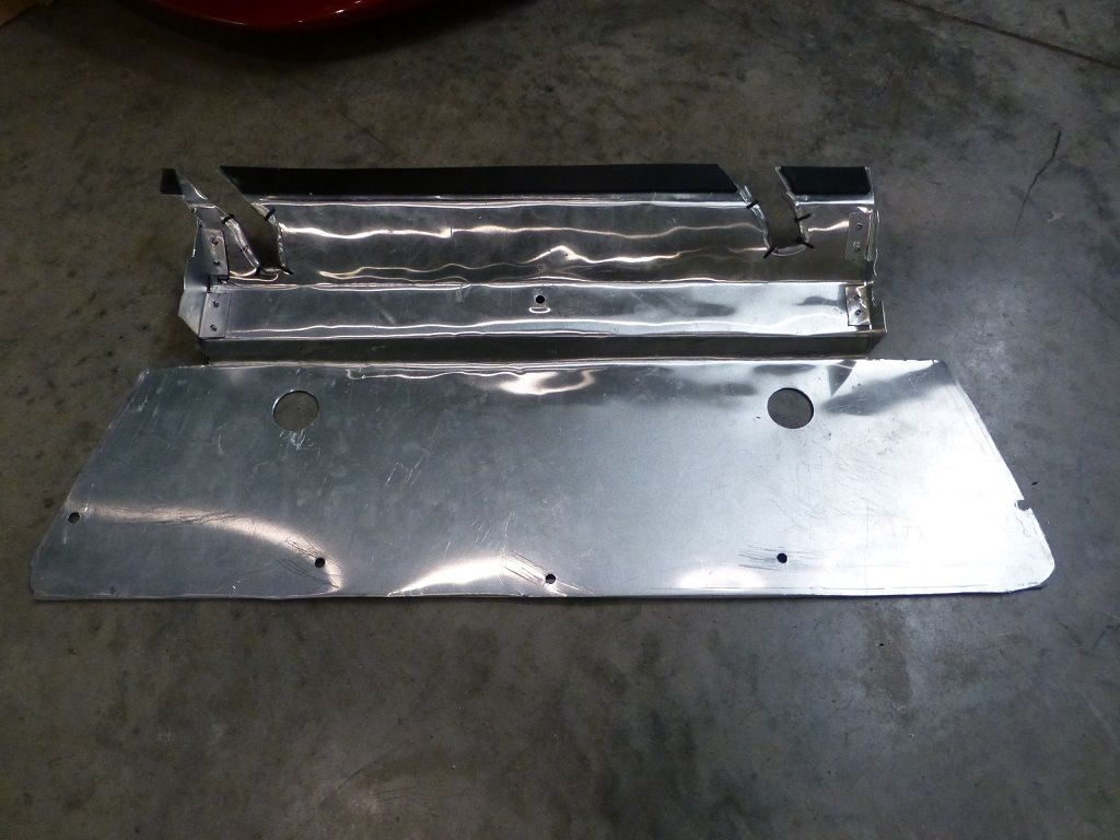
1: The bottom piece
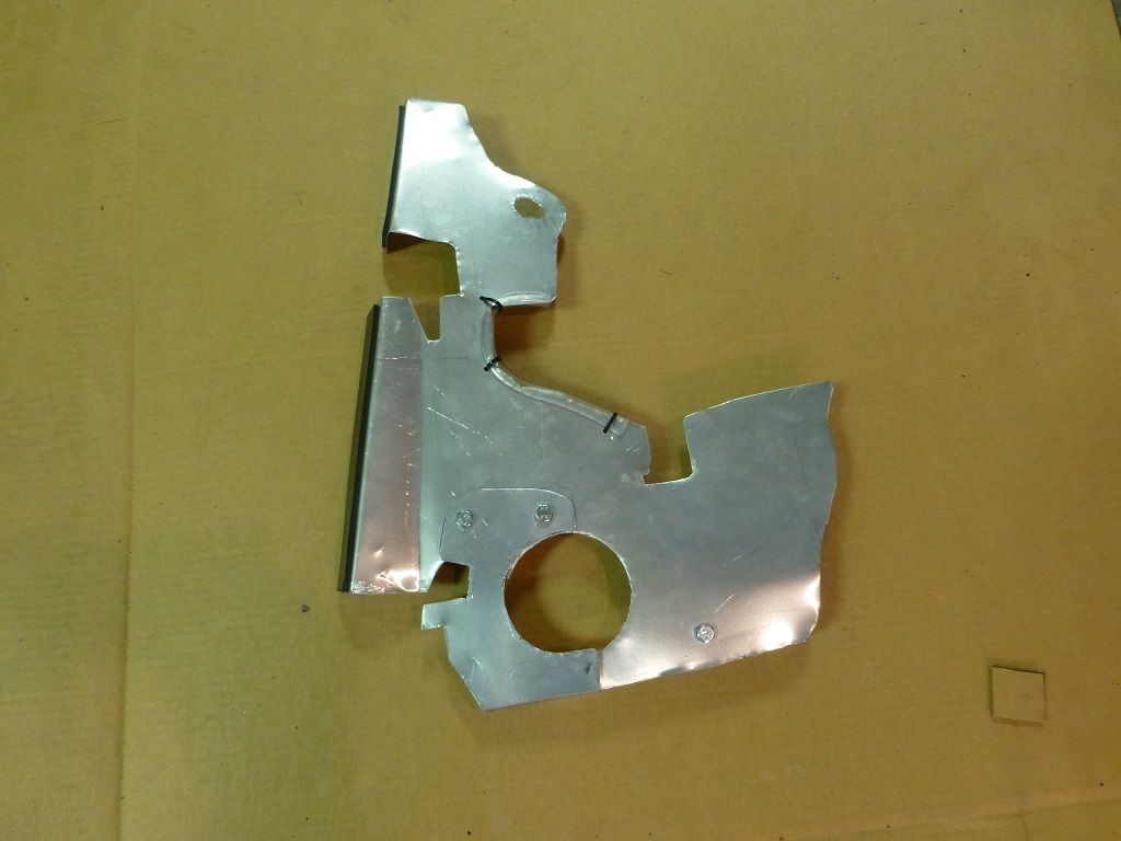
2 and 3: The two side pieces
4: The piece that seals the upper side of the bumper snout
5: The area to the left and right of the hood latch
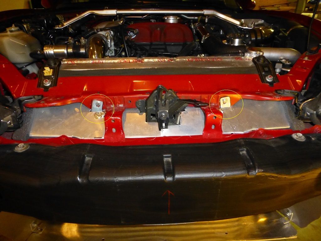
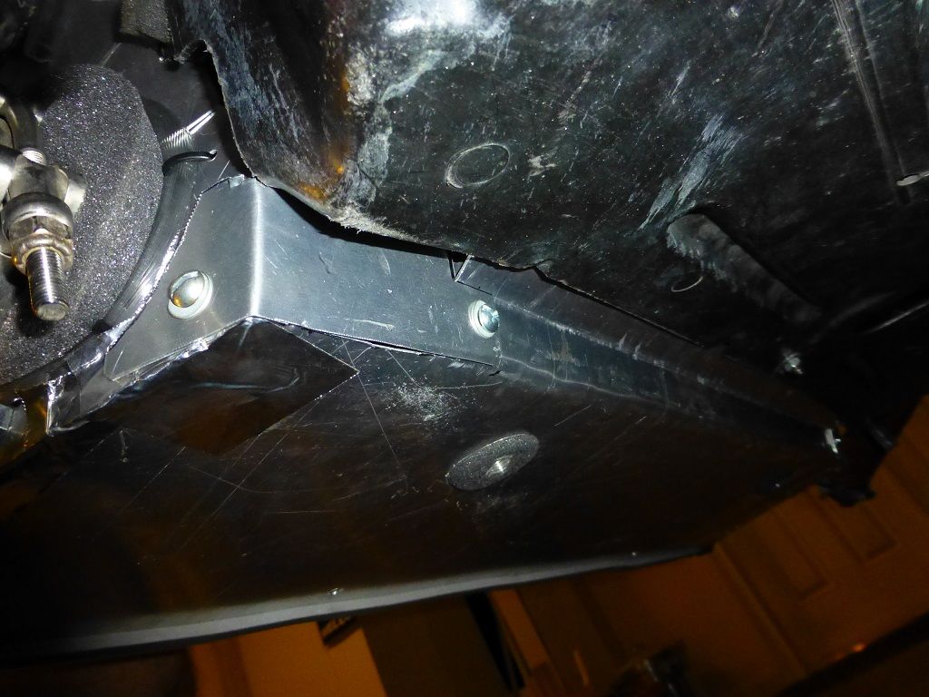
Piece 1 extends forward into the bumper and seals against the inside bottom of the bumper. The two bosses on the bottom of the intercooler stick through the round holes. The rear of this piece seals again the bottom or the radiator/fans. The black strip on the rear of the piece is rubber with adhesive on one side. I wanted to prevent metal from rubbing on metal. The 5 small holes on the forward part are used to attach it to the bumper.
The side pieces (2 and 3) were by far the most complicated and will fully test your patience. Each side is actually two pieces. These are the passenger side pieces. The approximate 1" 90 degree bend presses against the outside leading edge of the radiator. You can see the rubber on the part that "touches" the radiator. The forward (right side in the picture) extends into the bumper and seals against the inside forward most part of the bumper just outside of the snout opening.
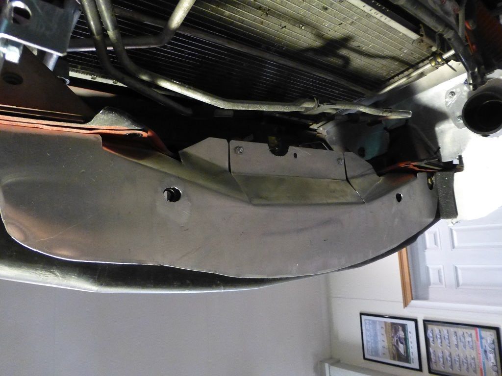
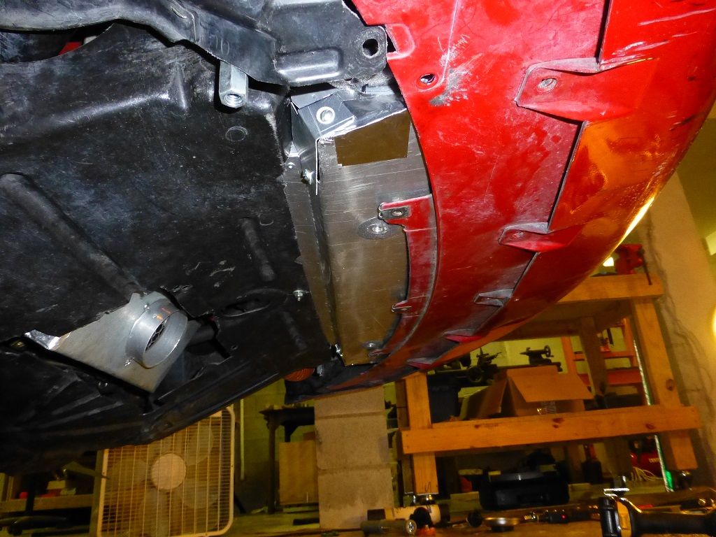
Pieces 4 and 5. This picture is from an odd angle, but it shows the areas you are trying to seal. This picture is looking straight up from underneath the car with no intercooler installed. The condenser is in the top of the pic. Piece 4 seals the gap at the top of the bumper and piece 5 seals to the left and right of the hood latch.
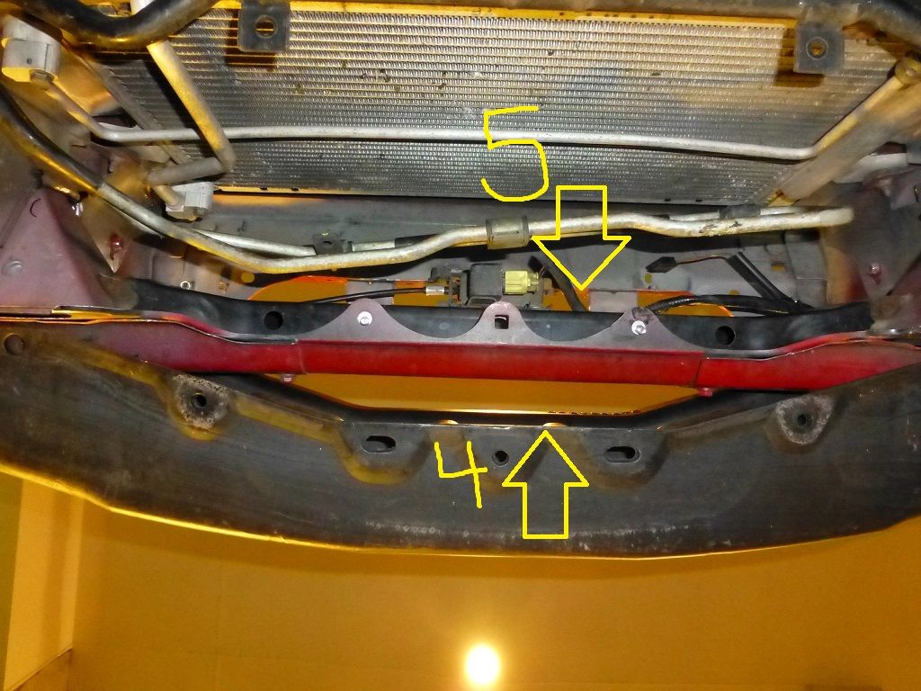
Piece 4 installed
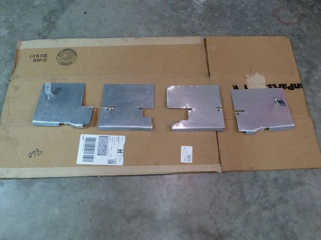
The pieces that seal the area to either side of the hood latch are actually 4 pieces.
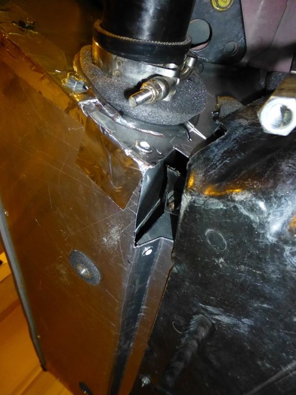
One of my goals was to have the ducting be completely independent of the plastic undertray. I have to pull it fairly often and didn't want to have to mess with the ducting when I did so. Of course, this complicates matters. I was about 95% successful. There are only 2 places where they interact and those are the forward outside mounting bolts for the undertray. I had to cut out the back corner of the ducting to allow the plastic undertray mounting tab could access it's OEM mounting bolt. You can see this part in the middle of the picture below. You can see a bolt sticking down and the undertray attaches here.
Once the undertray is installed, I have a small cover that screws in place. I used threaded inserts (the pop rivet kind) on the bottom ducting piece (part 1), so it only takes a second to install the pieces. Here is the cover piece installed.
And with everything installed.
I have many more detailed pics if anyone is interested.
First a little history-my wife and I both drive and instruct at HPDE/DE's- no wheel to wheel racing. We mainly drive with the PCA and our home track is Roebling Road in Savannah, GA. This car is a duel purpose car and acts as both a date night car and a track toy. Due to the nature of it being duel purpose, many compromises have had to be made. No parts have been removed and no body panels have been harmed in its evolution.
The car goes from date night clothing....
to it's track clothing.
The car's cooling system has been working pretty well except for the June events, where ambient temps approach 100 degrees. When my wife and I are both instructing, the car sees approximately (10) 20 minute sessions each day at a DE. It is also common for our run groups to be back to back, so often times, the car basically sees 40 minutes on track with a short 3 or so minute break for us to swap drivers.
The ducting is basically made up up 5 main pieces.
1: The bottom piece
2 and 3: The two side pieces
4: The piece that seals the upper side of the bumper snout
5: The area to the left and right of the hood latch
Piece 1 extends forward into the bumper and seals against the inside bottom of the bumper. The two bosses on the bottom of the intercooler stick through the round holes. The rear of this piece seals again the bottom or the radiator/fans. The black strip on the rear of the piece is rubber with adhesive on one side. I wanted to prevent metal from rubbing on metal. The 5 small holes on the forward part are used to attach it to the bumper.
The side pieces (2 and 3) were by far the most complicated and will fully test your patience. Each side is actually two pieces. These are the passenger side pieces. The approximate 1" 90 degree bend presses against the outside leading edge of the radiator. You can see the rubber on the part that "touches" the radiator. The forward (right side in the picture) extends into the bumper and seals against the inside forward most part of the bumper just outside of the snout opening.
Pieces 4 and 5. This picture is from an odd angle, but it shows the areas you are trying to seal. This picture is looking straight up from underneath the car with no intercooler installed. The condenser is in the top of the pic. Piece 4 seals the gap at the top of the bumper and piece 5 seals to the left and right of the hood latch.
Piece 4 installed
The pieces that seal the area to either side of the hood latch are actually 4 pieces.
One of my goals was to have the ducting be completely independent of the plastic undertray. I have to pull it fairly often and didn't want to have to mess with the ducting when I did so. Of course, this complicates matters. I was about 95% successful. There are only 2 places where they interact and those are the forward outside mounting bolts for the undertray. I had to cut out the back corner of the ducting to allow the plastic undertray mounting tab could access it's OEM mounting bolt. You can see this part in the middle of the picture below. You can see a bolt sticking down and the undertray attaches here.
Once the undertray is installed, I have a small cover that screws in place. I used threaded inserts (the pop rivet kind) on the bottom ducting piece (part 1), so it only takes a second to install the pieces. Here is the cover piece installed.
And with everything installed.
I have many more detailed pics if anyone is interested.
Reply
4
4
That's a pretty awesome first post. Only nit is that "duel" != "dual" (haha).
I recently constructed something really similar, but haven't driven with it yet. Hope it works as well as yours. Linky: https://www.miataturbo.net/build-thr...8/#post1244564
I recently constructed something really similar, but haven't driven with it yet. Hope it works as well as yours. Linky: https://www.miataturbo.net/build-thr...8/#post1244564
Reply
0
0


