

Post your DIY aero pics


Demand is light and the cool guy pricing only came with a big order. So I just send folks directly to APR now. When we get around to producing our frame rail mounts, we'll produce some matching foils to complete a PnP kit. Low priority right now though, sorry.
__________________


Reply
 0
0

0

Senior Member
Joined: Dec 2012
Posts: 624
Total Cats: 81
From: Charlotte, NC
Just finished mounting the new fiberglass front end. It's an E-prod setup, but the fenders are made to mount flush to the door. I was VERY tight on tire clearance and wanted to vent the rear fenders, so I just made some stanchions to hold them out and flex the fender slightly. Thankfully, the fiberglass is so damn thin, it has a good bit of flexibility and doesn't put up much of a fight. Nose and fenders come off in one piece, mounted to a pair of tubular frame rails after I cut most of the front end off.
Reply
0
0


Reply
0
0

Brooks Motorsports has some nice looking wings and seem pretty open to custom stuff. Last time I saw one of their wings was a few years ago before the company changed hands, and it was a little rough around the edges but overall pretty nice. The only real complaint I had was a very rough leading edge from the mold parting line, and they've supposedly changed the molds to eliminate that. I don't know anything about the foil profiles they're using, though.
-Ryan

Reply
0
0

Junior Member
Joined: Jun 2005
Posts: 286
Total Cats: 235
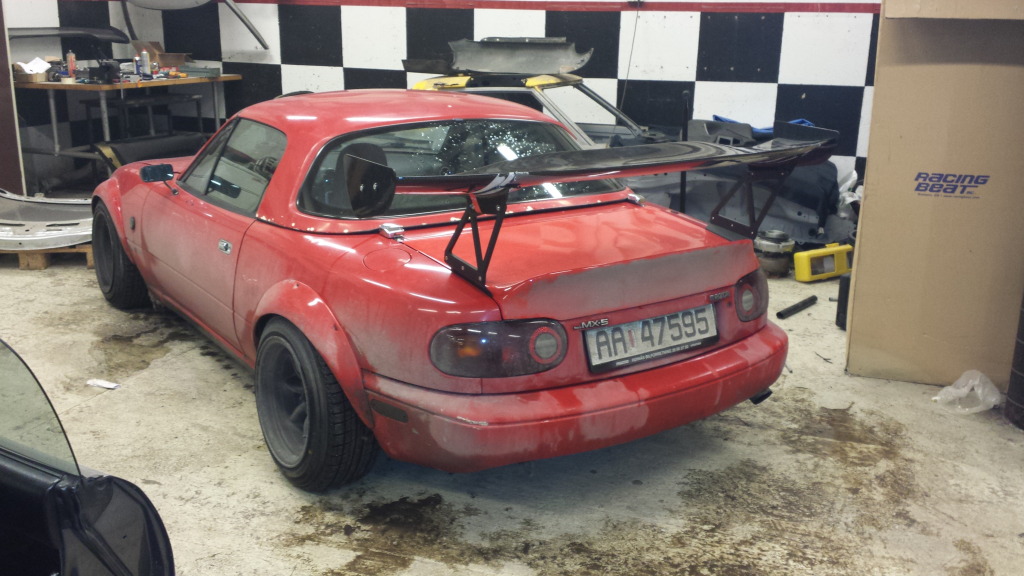
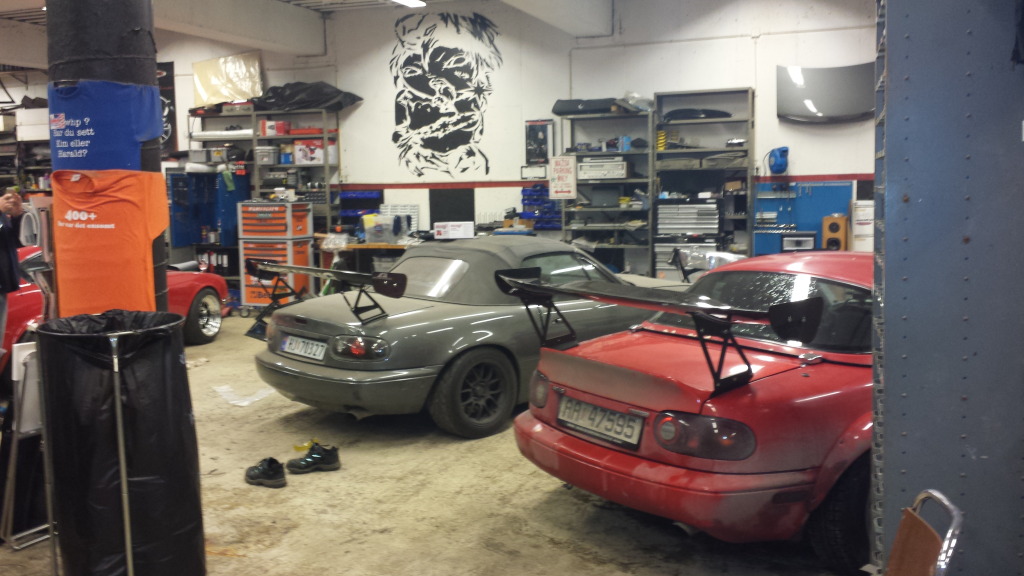
After trying my gt200 wing from the grey 400whp mx, on the stock(ish) powered red one, my friend had to have a wing too.
Shaved a clean 1.5 sec of pr lap on a 1.48 min lap on our local track(rudskogen , norway)
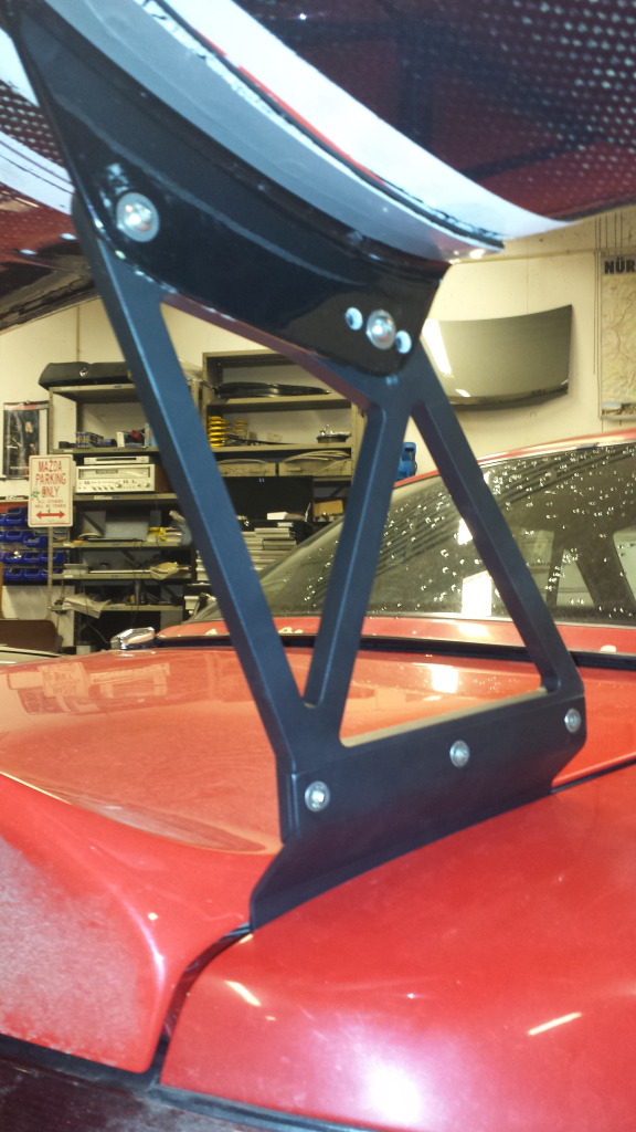
the wing on the red one is " china special " mounts are 4mm titanium plate(yup.. steel was heavy and he had access to titanium)
legs for the wing are custom made for this setup, and the mounts underneath the wing moved out to match..
Will complement with a frontsplitter similar to the one i have posted aerlier to balance it all out.
hope you guys approve of Einars new aero
Shaved a clean 1.5 sec of pr lap on a 1.48 min lap on our local track(rudskogen , norway)
the wing on the red one is " china special " mounts are 4mm titanium plate(yup.. steel was heavy and he had access to titanium)
legs for the wing are custom made for this setup, and the mounts underneath the wing moved out to match..
Will complement with a frontsplitter similar to the one i have posted aerlier to balance it all out.
hope you guys approve of Einars new aero


Reply
2
2

Junior Member
Joined: Dec 2011
Posts: 75
Total Cats: 3
I like it, did a similar set up with mine. Put my wing a bit higher but unfortunately my uprights bent under the downforce. I remember reading somewhere you should be able to sit on your wing without it shifting. Like you say the front splitter will help balance things. Then you play around with the wing angle.
I managed 1.13G on some bends in the morning. Only managed .99G in the afternoon without the wing after I bent things :( and like you my times were quicker too.
I managed 1.13G on some bends in the morning. Only managed .99G in the afternoon without the wing after I bent things :( and like you my times were quicker too.
Reply
0
0
-Ryan
Reply
0
0


Canards, anyone have info on these that goes beyond basic. I really only ever see non-aerofoil canards, basically just a flat profile sometimes curved a curve. I get 0.6sqft on each side, cant go wider than the rest of the front bodywork, cant extend more than 6" in front of the car. Area is measured by chord X length. 1 end of the canard must be mounted to a surface of the car (IE no front wings). So I can camber, and fatten the **** out of it to get all of the downforce without a real penalty besides drag, which I dont really care about.
Reply
0
0
Been working on trying to get my simulation to work right. So far I got the program to calculate the coefficient of drag to be .34 (actual .38). However, Autodesk Falcon is not consistent in its results. Either it gives a reasonable value near .34 or something ridiculous with successive trials. As such I have very little confidence in any results. I guess that is what I get for using freeware. The computer in my laboratory has Comsol on it which can do the calculation. Just need to find a time when it is not being used for micromagnetic simulations.
Reply
0
0

Usually inconsistent results= poor mesh.
To learn the software & validate your results you should start simple with something you can analytically solve with equations "easily". Then you can validate that you are using the system correctly and build complexity from there. Automated meshing tools are not always your friend.
Take this with a grain of salt. I haven't done CFD since college (4 yrs ago), but I do use quite a bit of FEA at work and poor meshes are always a cause of inconsistency.
Reply
0
0

The guy that made my lightweight hardtop and doors just came out with this for the NB.
97 06 N B Mazda Miata Fiberglass GT Wide Body Kit | eBay
97 06 N B Mazda Miata Fiberglass GT Wide Body Kit | eBay
Reply
0
0

I never really played much more with the software since I got busy with actually working on the car, then breaking just about everything on it at a trackday and subsequent repairs. The problem with the software was probably mesh size. I haven't been to up to date in buying any sort of technology, which is funny since the lab I am in deals with novel computing tech.
Reply
0
0

Junior Member
Joined: Dec 2012
Posts: 74
Total Cats: 45
From: Indianapolis
Usually inconsistent results= poor mesh.
To learn the software & validate your results you should start simple with something you can analytically solve with equations "easily". Then you can validate that you are using the system correctly and build complexity from there. Automated meshing tools are not always your friend.
Take this with a grain of salt. I haven't done CFD since college (4 yrs ago), but I do use quite a bit of FEA at work and poor meshes are always a cause of inconsistency.
To learn the software & validate your results you should start simple with something you can analytically solve with equations "easily". Then you can validate that you are using the system correctly and build complexity from there. Automated meshing tools are not always your friend.
Take this with a grain of salt. I haven't done CFD since college (4 yrs ago), but I do use quite a bit of FEA at work and poor meshes are always a cause of inconsistency.
For at least the cfd work I have done, I have found that a mesh under 5 million cells for half car model yields bad results. I usually fall in the range of 10-20 million cells using mesh dependency study depending on the complexity of the model.
Reply
0
0

The guy that made my lightweight hardtop and doors just came out with this for the NB.
97 06 N B Mazda Miata Fiberglass GT Wide Body Kit | eBay
97 06 N B Mazda Miata Fiberglass GT Wide Body Kit | eBay
Reply
0
0
This! Mesh quality is one of the most important aspects of quality cfd work. Start with the ahmed model to verify your can run the software correctly and create a decent mesh.
For at least the cfd work I have done, I have found that a mesh under 5 million cells for half car model yields bad results. I usually fall in the range of 10-20 million cells using mesh dependency study depending on the complexity of the model.
For at least the cfd work I have done, I have found that a mesh under 5 million cells for half car model yields bad results. I usually fall in the range of 10-20 million cells using mesh dependency study depending on the complexity of the model.
Reply
0
0
Junior Member
Joined: Dec 2012
Posts: 74
Total Cats: 45
From: Indianapolis
I would think there would be, but I do know as I do not use that software. I know in most meshing softwares for cfd, you have a lot of control over the mesh. Is that the only software you have access to?
Reply
0
0
Junior Member
Joined: Dec 2012
Posts: 74
Total Cats: 45
From: Indianapolis
Reply
0
0


